Method and Node Device for Fault Detection and Convergence in Ethernet
- Summary
- Abstract
- Description
- Claims
- Application Information
AI Technical Summary
Benefits of technology
Problems solved by technology
Method used
Image
Examples
embodiment 1
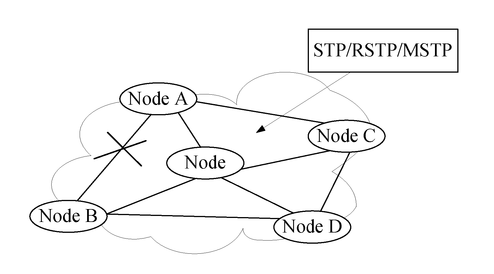
[0033]This embodiment takes a universal Ethernet (that is, Ethernet of any topology) as an example. First, the OAM protocol works in the Ethernet to detect a link fault between nodes. If the link fault is detected, protection switching is performed by using the STP. FIG. 5 illustrates a method for fault detection and convergence in an Ethernet. In block 101, a node in the Ethernet sends an OAM CC message to a neighboring node periodically to detect a fault on the link between the nodes.
[0034]FIG. 6 shows a structure of a universal Ethernet. In this Ethernet, each node sends an OAM CC message to its neighboring node to check whether the link between the nodes is normal.
[0035]In block 102 of FIG. 5, if the node receives no CC message from its neighboring node in the preset time, the link between the node and its neighboring node is faulty.
[0036]As shown in FIG. 6, if the link between node A and node B is faulty, node A receives no CC message from node B in the preset time; likewise, n...
embodiment 2
[0042]This embodiment takes an Ethernet ring (an Ethernet of a ring topology) as an example. In an Ethernet ring, after a link fault is detected through the OAM protocol, network convergence may be performed by using the RRPP. FIG. 7 illustrates a method for fault detection and convergence in an Ethernet. In block 201, a node in the Ethernet ring sends an OAM CC message to its neighboring node periodically. In block 202 of FIG. 7, if the node receives no CC message from its neighboring node in the preset time, the link between the node and its neighboring node is faulty. In block 203 of FIG. 7, the node performs network convergence by using the RRPP.
[0043]After the link fault is detected, the node performs network convergence by using the RRPP, as detailed below. The node sets its faulty port to the Down state according to the RRPP, and sends a message indicating the link fault to the master node in the Ethernet ring through another port. After receiving the message indicating the l...
embodiment 3
[0049]As shown in FIG. 10, a node device provided in this embodiment includes a detecting module 301 configured to detect a link fault according to the OAM protocol. A converging module 302 is configured to perform network convergence by using a Layer 2 network protection protocol according to the type of the Ethernet after the detecting module 301 detects the link fault.
[0050]As shown in FIG. 11, the detecting module 301 may include a first sending unit 3011, configured to send an OAM CC message to a neighboring node device of the node device periodically. A determining unit 3012 is configured to determine that the link between the node device and the neighboring node device is faulty if the node device receives no CC message sent by the neighboring node device of the node device in the preset time.
[0051]Further, if the Ethernet is a universal Ethernet, the converging module 302 may include a second sending unit 3021 configured to send a first message indicating the link fault to o...
PUM
 Abstract
Description
Claims
Application Information
 - R&D
- Intellectual Property
- Life Sciences
- Materials
- Tech Scout
- Unparalleled Data Quality
- Higher Quality Content
- 60% Fewer Hallucinations
Browse by: Latest US Patents, China's latest patents, Technical Efficacy Thesaurus, Application Domain, Technology Topic, Popular Technical Reports.
© 2025 PatSnap. All rights reserved.Legal|Privacy policy|Modern Slavery Act Transparency Statement|Sitemap|About US| Contact US: help@patsnap.com


