Gas turbine fuel oil and production method thereof and power generation method

a technology of gas turbines and fuel oil, which is applied in the direction of hydrocarbon distillation, liquid carbonaceous fuels, fuels, etc., can solve the problems of large amount of energy outwardly discharged in the form of greenhouse gas without being recovered, certain amount of sox to be present in exhaust gas or flue gas discharged therefrom, and the system is deteriorating in power generation efficiency

Inactive Publication Date: 2007-10-02
JGC CORP
View PDF33 Cites 49 Cited by
  • Summary
  • Abstract
  • Description
  • Claims
  • Application Information

AI Technical Summary

Benefits of technology

[0026]In addition, in accordance with a further aspect of the present invention, a power generation method is provided. The power generation method includes the steps of driving a gas turbine using gas turbine fuel oil produced as described above as fuel therefor to carry out power generation and using high-temperature exhaust gas discharged from the gas turbine as a heat source for a waste heat recovery boiler and driving a steam turbine by means of steam generated in the waste heat recovery boiler, resulting in power generation being carried out.

Problems solved by technology

However, such a system is deteriorated in power generation efficiency.
Thus, it causes a large part of energy to be outwardly discharged in the form of greenhouse gas without being recovered.
In addition, it causes a certain amount of SOx to be present in exhaust gas or flue gas discharged therefrom.
Although the exhaust gas is subject to flue gas desulfurization, SOx is partially discharged to an ambient atmosphere, leading to environmental pollution.
Unfortunately, this leads to an increase in cost of equipment.
Now, an environmental problem comes to notice in the art.
Unfortunately, in power generation using gas turbine fuel oil, arrangement of the flue gas desulfurization unit causes a deterioration in power generation efficiency due to a pressure loss, so that it is required to minimize a sulfur content of gas turbine fuel oil.
Thus, the techniques of the former Japanese publication cause the amount of firing of oil to be considerably restricted in the atmospheric distillation or vacuum distillation, to thereby fail to increase the amount of light oil or light distillate to be fed to the gas turbine or the amount of gas turbine fuel oil.
Also, when it is applied to crude oil which is readily available and increased in sulfur content, recovery of light oil or light residue in the same amount causes a sulfur content of the light oil to exceed a specified level, so that it is unsuitable for use as fuel oil for a gas turbine.
Thus, it is forced to decrease recovery of the light oil, resulting in application to the crude oil being technically and economically disadvantageous.
However, the techniques are constructed so as to treat crude oil at a low sulfur content, so that application of the techniques to crude oil at a high sulfur content is considerably restricted.
Unfortunately, this causes excessive cracking of light oil in the crude oil, resulting in LPG or the like being contained in a large amount in fuel oil for a gas turbine, so that storage of the fuel oil causes a part thereof to be gasified.
Also, the reaction temperature and reaction pressure are caused to be increased, so that a reaction vessel for the hydrotreating is complicated in structure and increased in manufacturing cost.
Further, an increase in reaction time requires large-sizing of a catalyst carrier, leading to large-sizing of the reaction vessel and an increase in consumption of a catalyst.

Method used


Image

  • Gas turbine fuel oil and production method thereof and power generation method
  • Gas turbine fuel oil and production method thereof and power generation method
  • Gas turbine fuel oil and production method thereof and power generation method

Examples


example 1

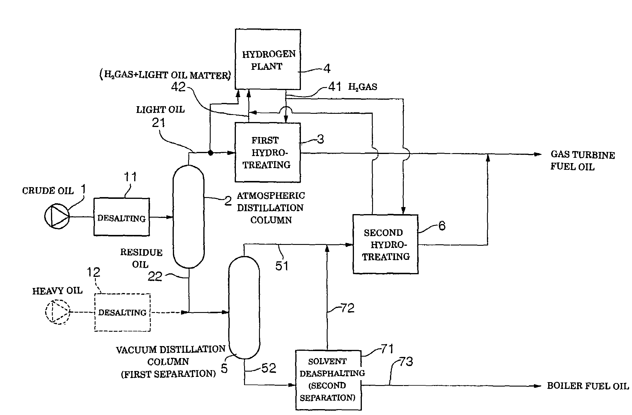
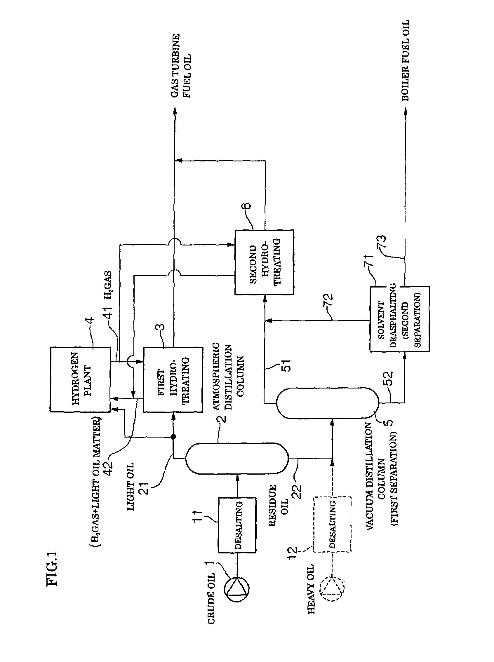
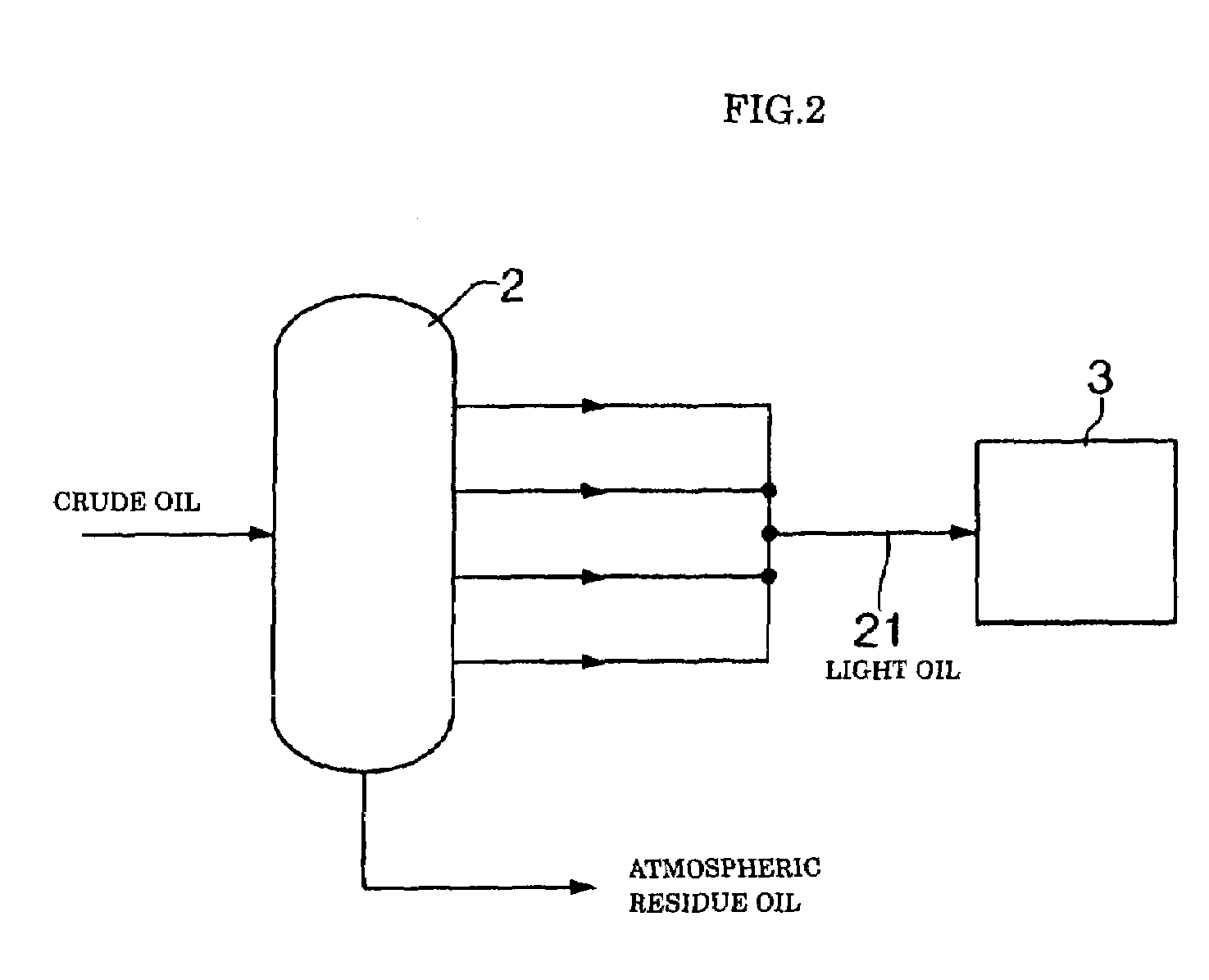
[0079]Arabian light crude oil (S content: 1.77% by weight) which is most readily available in the art was used as feed oil, to thereby produce gas turbine fuel oil by means of the system shown in FIG. 1. More particularly, the crude oil was separated into light oil or light distillate 21 of 350° C. or less in boiling point and heavy oil or residue 22 above 350° C. in boiling point and a hydrogen gas pressure in the first hydrotreating step was set to be 45 kg / cm2, resulting in gas turbine fuel oil being produced. Also, the vacuum distillation step provided a light oil matter 51 of 565° C. or less in boiling point (boiling point under an atmospheric pressure) and a heavy oil matter 52 having a boiling point above 565° C. by separation. In addition, a hydrogen gas pressure in the second hydrotreating step was set to be 55 kg / cm2, to thereby obtain gas turbine fuel oil, which was then mixed with the gas turbine fuel oil produced in the first hydrotreating step. Any alkaline metal, alka...

example 2

[0083]Of Middle East crude oil, Oman crude oil is known to have a relatively low sulfur content. Such Oman crude oil was used for producing gas turbine fuel oil by means of the system shown in FIG. 1. Oman crude oil has a sulfur concentration of 0.94% by weight, thus, it corresponds to low-sulfur crude oil described in Japanese Patent Application Laid-Open Publication No. 207179 / 1994. In Example 2, the crude oil was subject to atmospheric distillation, to thereby be separated into light oil or light distillate 21 of 350° C. or less in boiling point and heavy oil or residue 22 having a boiling point above 350° C. Also, a hydrogen gas pressure in the first hydrotreating step was set to be 40 kg / cm2, resulting in gas turbine fuel oil being produced. Also, the vacuum distillation step provided a light oil matter 51 of 565° C. or less in boiling point (boiling point under an atmospheric pressure) and a heavy oil matter 52 having a boiling point above 565° C. by separation. In addition, a...


PUM

PropertyMeasurementUnit
temperatureaaaaaaaaaa
boiling pointaaaaaaaaaa

Abstract

Feed oil is subject to atmospheric distillation, to thereby be separated into light oil or light distillate and atmospheric residue oil. The light distillate is catalytically contacted with pressurized hydrogen in the presence of a catalyst, resulting in a first hydrotreating step being executed. In this instance, various fractions of the light distillate produced in the atmospheric distillation are subject to hydrotreating in a lump. The atmospheric residue oil is then separated into a light matter and a heavy matter. The light matter is subject to second hydrotreating in the presence of a catalyst to produce refined oil (light matter), which is mixed with refined oil produced in the first hydrotreating to prepare a mixture. The mixture is used as gas turbine fuel oil.

Description

TECHNICAL FIELD[0001]This invention relates to fuel oil for a gas turbine, and more particularly to gas turbine fuel oil used for power generation by gas turbine, a method for producing such gas turbine fuel oil and a power generation method using such gas turbine fuel oil.BACKGROUND ART[0002]In general, oil thermal power generation is adapted to generate steam at a high pressure in a boiler using crude oil and / or heavy oil as a fuel for the boiler, to thereby rotate a steam turbine by means of the thus-generated steam, leading to power generation. However, such a system is deteriorated in power generation efficiency. Currently, a high-efficiency large-sized oil-fired boiler is developed, however, it merely exhibits generation efficiency as low as about 40%. Thus, it causes a large part of energy to be outwardly discharged in the form of greenhouse gas without being recovered. In addition, it causes a certain amount of SOx to be present in exhaust gas or flue gas discharged therefro...

Claims


Application Information

Patent Timeline
Patent Type & Authority Patents(United States)
IPC IPC(8): C10G65/02C10L1/04C10G7/00C10G7/06C10G45/00C10G65/04C10G65/16C10G67/00
CPCC10G65/04C10G65/16C10G67/00C10G2300/4025C10G2300/302C10G2300/107C10G2300/202C10G2300/205C10G2300/1033C10G65/00
Inventor OKADA, TSUYOSHIMASHIKO, YOSHINORITOKUDA, SHINICHISASAKI, TOMOYOSHIIMURA, KOZOINOMATA, MAKOTOTANUMA, TOSHIO
Owner JGC CORP
Why Eureka
Try Eureka