Cold storage heat exchanger

a heat exchanger and cold storage technology, applied in indirect heat exchangers, domestic cooling devices, lighting and heating devices, etc., can solve the problems of affecting the comfort of the vehicle interior, affecting the efficiency of fuel consumption, and limiting the temperature change of blown-out air, so as to achieve high melting point and low melting point

Inactive Publication Date: 2015-06-18
DENSO CORP
View PDF7 Cites 18 Cited by
  • Summary
  • Abstract
  • Description
  • Claims
  • Application Information

AI Technical Summary

Benefits of technology

[0015]According to the present disclosure, the cold storage materials having different melting points are divided from each other and accommodated respectively in the cold storage container. The cold storage material having a high melting point is disposed on an upstream side of the cold storage material having a low melting point in a flow direction of air. Accordingly, when the temperature of the refrigerant is, for example, equal to or lower than, the melting point of the high melting point cold storage material, and is equal to or higher than the melting point of the low melting point cold storage material, only the high melting point cold storage material is solidified. As a result, even though the refrigerant temperature is high, the cold storage can be carried out. When the refrigerant temperature becomes further low, all the cold storage materials are solidified. Thus, the cold can be stored in stages in accordance with the refrigerant temperature. Therefore, a cold storage function can be maintained in a wider range of air temperature.

Problems solved by technology

Such an idle reduction vehicle has an issue that the refrigeration cycle device stops while the vehicle is stopped (while its engine is stopped), so that comfortableness of the vehicle interior is impaired.
If the engine is restarted even while the vehicle is stopped to maintain an air-conditioning feeling, there is also an issue that an improvement in fuel efficiency is prevented.
Accordingly, a temperature change of blown-out air can be limited to maintain an air-conditioning feeling until the cold storage material is completely melted.
However, in case of use under temperature environment where the cold storage material cannot be solidified while idling is stopped, a sufficient amount of cold air cannot be accumulated.
Thus, because cold air cannot be released for a long time, there is an issue that an idle stop time is shortened to maintain an air-conditioning feeling.

Method used


Image

  • Cold storage heat exchanger
  • Cold storage heat exchanger
  • Cold storage heat exchanger

Examples


first embodiment

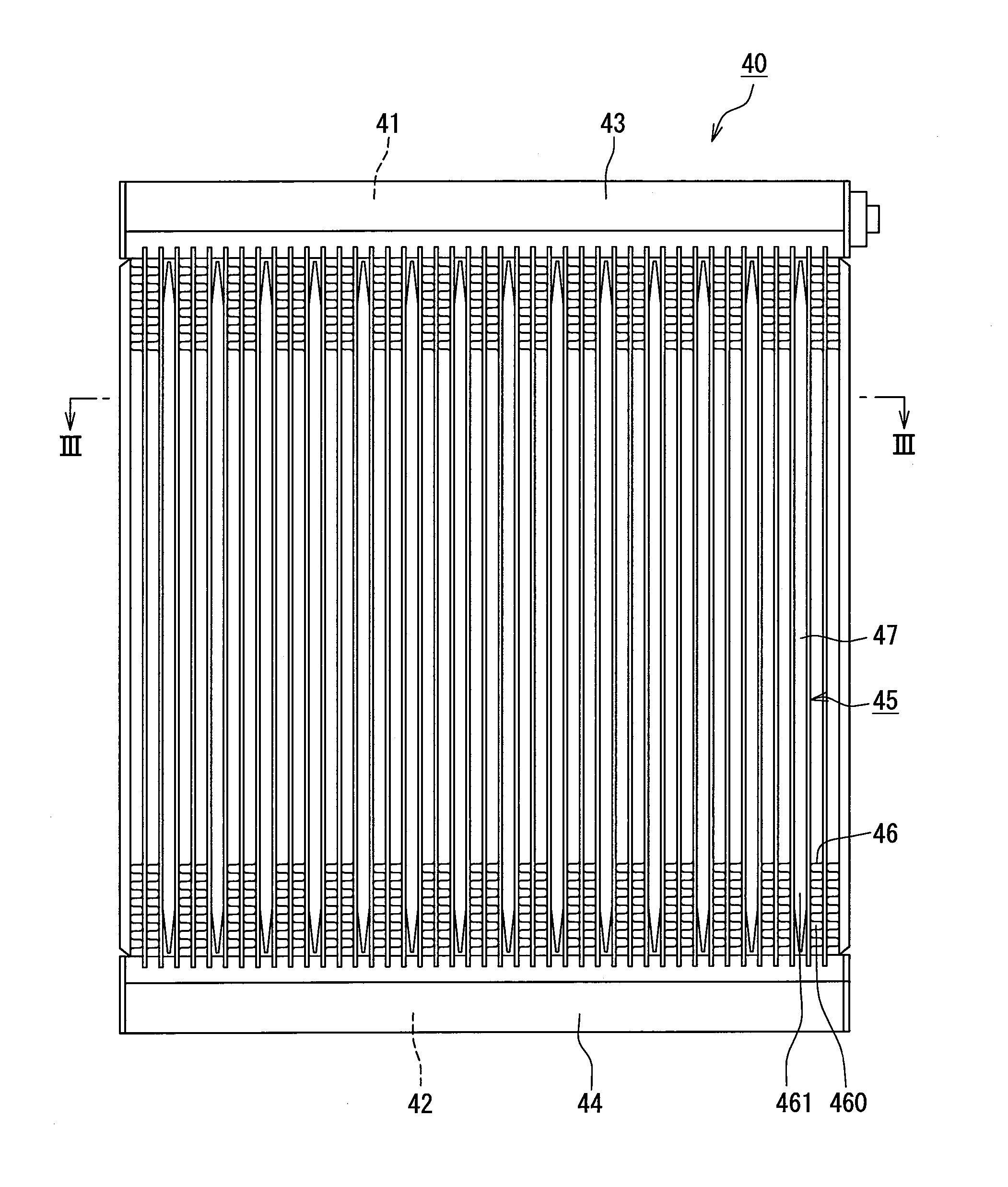
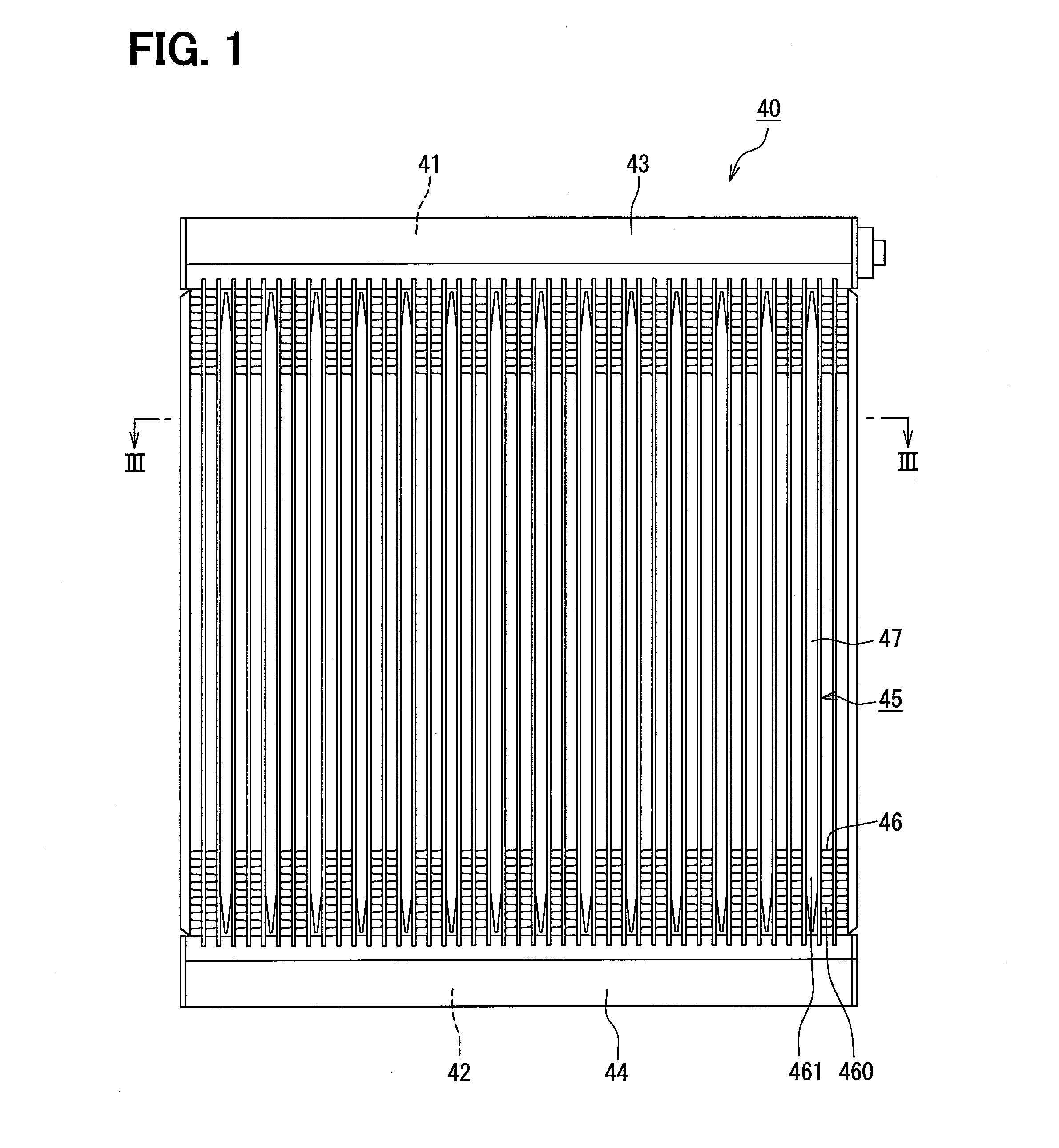
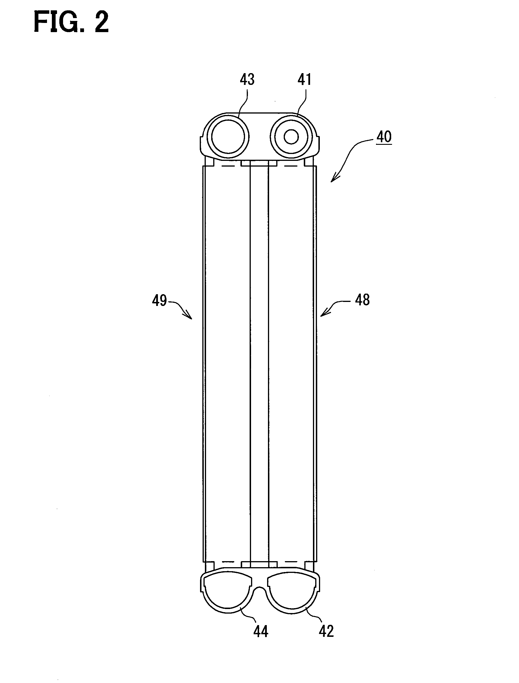
[0035]A first embodiment will be described in reference to FIGS. 1 to 5. An evaporator 40 constitutes a refrigeration cycle system (not shown). The refrigeration cycle system is used for, for example, an air-conditioning system for a vehicle. The refrigeration cycle system includes, although not shown, a compressor, a radiator, a decompressor, and the evaporator 40. These components are connected through a pipe annularly to constitute a refrigerant circulation passage. The compressor is driven by a power source for vehicle traveling. Accordingly, when the power source stops, the compressor also stops. The compressor draws in the refrigerant from the evaporator 40, compresses the refrigerant, and discharges the refrigerant into the radiator. The radiator cools high-temperature refrigerant. The radiator is also referred to as a condenser. The decompressor decompresses the refrigerant cooled by the radiator. The decompressor can be provided by a fixed throttle, a temperature type expan...

second embodiment

[0063]A second embodiment will be described in reference to FIGS. 6 and 7. The present embodiment is characterized in that cold storage cases 60A are arranged to be in contact with each other. Because of such a configuration in which the cold storage cases 60A are in contact, the space can be used more effectively. Accordingly, the amount of cold storage materials 50a, 50b, with which a cold storage container 47 can be filled, can be made large. Operation and effects of the other configuration are similar to the above-described first embodiment.

third embodiment

[0064]A third embodiment will be described in reference to FIG. 8. The present embodiment is characterized in that the inside of a cold storage container 47C is divided by a partition 70, and that cold storage materials 50a, 50b having different melting points are accommodated respectively in the divided spaces. One sealing port 61, through which the cold storage material 50a, 50b is sealed, is provided for this cold storage container 47C. Accordingly, two types of the cold storage materials 50a, 50b are sealed through the one sealing port 61. As a result, the configuration is simplified, and is easily handled as the cold storage container 47C. The sealing port 61 is provided at the outer periphery of the cold storage container 47C on an upstream side or on a downstream side in a flow direction of air, and is provided on a leeward side in the present embodiment. Because of such a configuration, the space can be used more effectively. Accordingly, the amount of the cold storage mater...


PUM


Abstract

A cold storage heat exchanger for exchanging heat with air flowing therearound includes a refrigerant passage in which refrigerant flows, and a cold storage container that accommodates therein cold storage materials which exchanges heat with the refrigerant flowing through the refrigerant passage and retains the amount of heat from the refrigerant. The cold storage materials having different melting points are accommodated in the cold storage container.

Description

CROSS REFERENCE TO RELATED APPLICATION[0001]This application is based on Japanese Patent Application No. 2012-135042 filed on Jun. 14, 2012, the disclosure of which is incorporated herein by reference.TECHNICAL FIELD[0002]The present disclosure relates to a cold storage heat exchanger used for a refrigeration cycle device.BACKGROUND ART[0003]Conventionally, a refrigeration cycle device is used for an air-conditioning system. An attempt is made to provide limited refrigerated air-conditioning even in a state where this refrigeration cycle device is stopped. For example, in an air-conditioning system for a vehicle, the refrigeration cycle device is driven by an engine for traveling. For this reason, when the engine stops while the vehicle is making a brief stop, the refrigeration cycle device is stopped. An “idle reduction vehicle” which stops its engine while the vehicle is stopped, waiting for a traffic light, for example, in order to improve fuel efficiency increases in number. Suc...

Claims


Application Information

Patent Timeline
Patent Type & Authority Applications(United States)
IPC IPC(8): F25D17/00
CPCF25D17/00F25B39/022F25B2400/24F28D1/05383F28D20/026F28D2020/0013F28D2021/0071Y02E60/14
Inventor DANJYO, TAKASHIYAMADA, ATSUSHIINOUE, SEIJINISHIDA, SHIN
Owner DENSO CORP
Why Eureka
Try Eureka