Negative electrode for lithium ion secondary battery, production method thereof and lithium ion secondary battery comprising the same

Active Publication Date: 2006-06-22
PANASONIC CORP
View PDF2 Cites 78 Cited by
  • Summary
  • Abstract
  • Description
  • Claims
  • Application Information

AI Technical Summary

Benefits of technology

[0062] How the oxygen ratio of the interface between the first layer 1a and the second layer 1b varies depends on the production method of the active material layer.
[0063] The first layers 1a and the second layers 1b positioned at a certain depth from the surface in the active material layer are not necessarily a layer occupying the entire area at a given depth in a width direction and/or a length direction of the active material layer, as shown in FIG. 2. In short, the first layers 1a and the second layers 1b may be a non-continuous layer partially having a defect portion. In this case, the maximum width of the defect portion is preferably not greater than 1 μm. The reason therefor is the same as that given when the maximum thicknesses of the first layer 1a and the second layer 1b were specified previously above.
[0064] In this case also, as long as the thicknesses of the first layer 1a and the second layer 1b fall within the previously-mentioned range, the advantages of the present invention are not impaired.
[0065]FIG. 1 shows a case in which the first layers 1a and the second layers 1b are parallel to a length direction (and a width direction) of the current collector. As shown in FIG. 3, the first layers 1a and the second layers 1b may be tilted at a certain angle relative to a length direction and/or a width direction of the current collector. Even when the first and second layers are tilted, the advantages of the present invention can be obtained.
[0066] The negative electrode for a lithium ion secondary battery of the present invention does not require the inclusion of a carbon material. As such,

Problems solved by technology

Graphite materials, however, have a small capacity per unit weight of 372 mAh/g, and a further increase in capacity cannot be expected.
A large volume change of active material results in cracking of active material particles, insufficient contact between active material and current collector, etc, which shortens charge/discharge cycle life.
The formation of such film increases the interface resistance between the active material and the electrolyte, which is considered as a major cause for short charge/discharge cycle life.
However, the negative electrodes disclosed in the above-mentioned prior art references suffer from various problems.
For example, the present inventors examined the negative electrode disclosed by Japanese Laid-Open Patent Publication No. 2002-83594 only to find that lithium ion conductivity in the silicon was low, and that polarization increased when charge/discharge was performed at a high current value (i.e., high-load charge/discharge or high rate charge/discharge), resulting in a low discharge capacity.
In a silicon thin film, in particular, a large concentration gradient of lithium is produced in the thickness direction, and the capacity decreases easily.
Further, because silicon has an extremely large expansion coefficient, a negative electrode comprising silicon is highly deformed so that the electrode group having positive and negative electrodes disposed opposite to each other is buckled.
However, this requires considerable costs because additional steps are necessary such as a step of forming silicon into a columnar structure or a step of performing heat treatment for diffusing copper in the silicon.
Also, because the irreversible capacity is large, the capacity of the negative electrode is smaller than that of the positive electrode so that the battery capacity becomes significantly low.
From these reasons, the negative electrode of Japanese Patent Publication No. 2997741 fails to take advantage of the characteristics of high-capacity silicon and to provide a capacity as expected.
A further problem arises when the negative electrode contains a carbon material as a conductive material: propylene carbonate cannot be used as a solvent for electrolyte, because propylene carbonate is de

Method used


Image

  • Negative electrode for lithium ion secondary battery, production method thereof and lithium ion secondary battery comprising the same
  • Negative electrode for lithium ion secondary battery, production method thereof and lithium ion secondary battery comprising the same
  • Negative electrode for lithium ion secondary battery, production method thereof and lithium ion secondary battery comprising the same

Examples


Example

EXAMPLE 1

(Battery 1)

(i) Production of Positive Electrode

[0105] With 100 parts by weight of lithium cobalt oxide (LiCoO2) having an average particle size of 10 μm was mixed 3 parts by weigh of acetylene black as a conductive material to prepare a mixture. The resulting mixture was mixed with a N-methyl-2-pyrrolidone (NMP) solution of polyvinylidene fluoride (PVDF) as a binder such that 4 parts by weight of PVDF was added to the mixture, followed by kneading to prepare a positive electrode material mixture paste. The obtained positive electrode material mixture paste was applied onto both surfaces of a current collector sheet made of an aluminum foil, followed by drying and rolling to produce a positive electrode.

(ii) Production of Negative Electrode

[0106] The process for producing a negative electrode will be described later below.

(iii) Production of Battery

[0107] A 17500-type cylindrical battery as shown in FIG. 6 was produced using the above-produced positive electrode a...

Example

EXAMPLE 2

[0145] In this example, comparisons were made between batteries having a propylene carbonate (PC)-containing electrolyte and batteries having a non-PC-containing electrolyte in terms of initial capacity, charge / discharge efficiency and discharge capacity ratio at −10° C.

(Batteries 2 and 3)

[0146] Two different electrolytes were prepared: an electrolyte prepared by dissolving LiPF6 in a solvent mixture of propylene carbonate (PC) and dimethyl carbonate (DMC) at a volume ratio of 6:4 at a LiPF6 concentration of 1 mol / L; and another electrolyte prepared by dissolving LiPF6 in a solvent mixture of EC and DMC at a volume ratio of 1:3 at a LiPF6 concentration of 1 mol / L.

[0147] Batteries 2 and 3 were produced in the same manner as the battery 1 was produced except that the above two different electrolytes were used. The battery 2 included the electrolyte containing the solvent mixture of PC and DMC. The battery 3 included the electrolyte containing the solvent mixture of EC an...

Example

EXAMPLE 3

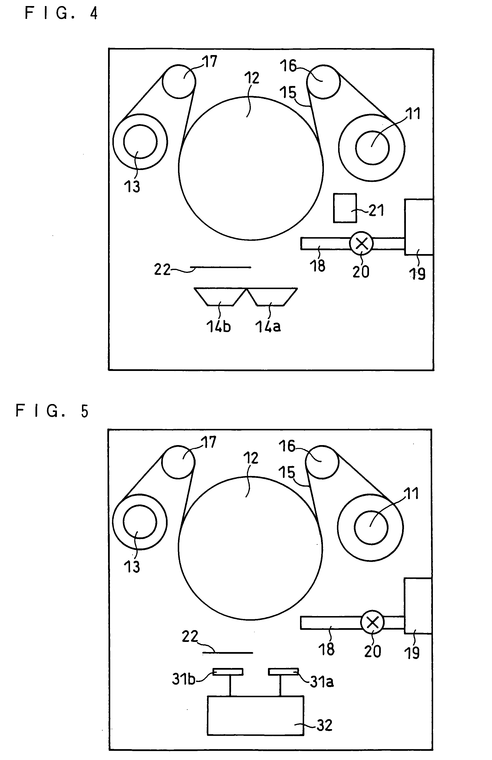
[0170] In this example, an investigation was carried out on the effective range of oxygen ratio in the first layer with no or a low oxygen ratio and the effective range of oxygen ratio in the second layer with a higher oxygen ratio. The investigation was performed by changing the flow rate of the oxygen gas introduced into the vacuum chamber of the vapor deposition equipment shown in FIG. 4 and changing the oxygen gas supply time.

(Battery 4)

[0171] A battery 4 was produced in the same manner as the battery 1 was produced except that, in the production of the negative electrode, the flow rate of the oxygen gas was set at 30 sccm. The pressure in the vacuum chamber was 1.8×10⁻⁴ Torr during the supply of the oxygen gas, and 6.0×10⁻⁵ Torr during the interval of the supply of the oxygen gas.

[0172] The negative electrode active material layer formed on each surface of the current collector had a thickness of 7.1 μm. The first layer and the second layer each had a thickness of...


PUM


Abstract

A negative electrode for a lithium ion secondary battery including a current collector and an active material layer carried on the current collector, wherein the active material layer includes a first layer and a second layer alternately laminated in a thickness direction of the active material layer, and wherein the first layer includes silicon or silicon and a small amount of oxygen and the second layer includes silicon and a larger amount of oxygen than the first layer. With the use of the negative electrode, it is possible to provide a high capacity lithium ion secondary battery having excellent high rate charge/discharge characteristics and superior cycle characteristics.

Description

FIELD OF THE INVENTION [0001] The present invention relates to a lithium ion secondary battery, and more particularly to a negative electrode therefor and a method for producing the negative electrode. BACKGROUND OF THE INVENTION [0002] Attention has been given to lithium ion secondary batteries as a power source for driving electronic equipment. Negative electrodes for lithium ion secondary batteries comprising a graphite material have an average potential during the desorption of lithium ions of about 0.2 V (vs. Li / Li+) and exhibit a relatively flat potential. This potential is lower than that of negative electrodes comprising hard carbon, and therefore equipment that requires high voltage and voltage flatness currently employs, as the power source, lithium ion secondary batteries comprising negative electrodes including a graphite material. Graphite materials, however, have a small capacity per unit weight of 372 mAh / g, and a further increase in capacity cannot be expected. [0003...

Claims


Application Information

Patent Timeline
IPC IPC(8): H01M4/38H01M4/48H01M4/04H01M4/131H01M4/1391H01M4/1395H01M4/485H01M4/52H01M4/525H01M10/0525H01M10/0587H01M10/36
CPCH01M4/0426H01M4/131H01M4/1391H01M4/1395H01M4/366H01M4/38H01M4/485H01M4/525H01M10/0525H01M10/0587H01M2004/027Y02E60/122H01M4/386Y02E60/10Y02P70/50H01M4/02H01M4/58
Inventor KOGETSU, YASUTAKAHONDA, KAZUYOSHISATO, TOSHITADAYOSHIZAWA, HIROSHI
Owner PANASONIC CORP
Why Eureka
Try Eureka