Target illuminating assembly having integrated magazine tube and barrel clamp with laser sight

a technology of laser sight and target illuminating assembly, which is applied in the direction of sighting devices, weapon components, weapons, etc., can solve the problems of reducing the capacity of firearm magazine, affecting the effect of holstering the handgun, and affecting the ability of the firearm to be holstered

Inactive Publication Date: 2007-02-22
LMD APPL SCI LLC
View PDF26 Cites 41 Cited by
  • Summary
  • Abstract
  • Description
  • Claims
  • Application Information

AI Technical Summary

Benefits of technology

[0013] The present invention provides a target illuminating assembly having an integrated magazine tube and barrel clamp with a laser sight, wherein capacity of the firearm magazine is not reduced.
[0018] In a further configuration, the target illuminator can be used to temporarily blind or disorient a target. For example, the target illuminator can have a sufficient brightness combined with a pulse or flash rate to provide a non lethal weapon with respect to the target such as by dazing or dazzling the target so as to impart temporary flash blindness, or disorientation.

Problems solved by technology

However, it is awkward and restrictive to hold a flashlight in one hand and a weapon in the other.
However, these devices can interfere with gripping the handgun, render holstering the handgun difficult, and require either that the flashlight be switched on, or actuated, with a hand other than the gripping hand or by a dedicated switch disposed on the handgrip.
While a laser sighting device provides an aiming function, it does not provide an illuminating function.
However, a drawback to this approach is that a physical connection between the handgrip and the front part of the frame of the weapon is required to switch the laser and flashlight on from the handgrip.
Such a connection, whether by electrical wiring, optical waveguide, or mechanical link adds weight, may require undue modification of the weapon, and can be inconvenient.

Method used


Image

  • Target illuminating assembly having integrated magazine tube and barrel clamp with laser sight
  • Target illuminating assembly having integrated magazine tube and barrel clamp with laser sight
  • Target illuminating assembly having integrated magazine tube and barrel clamp with laser sight

Examples


Embodiment Construction

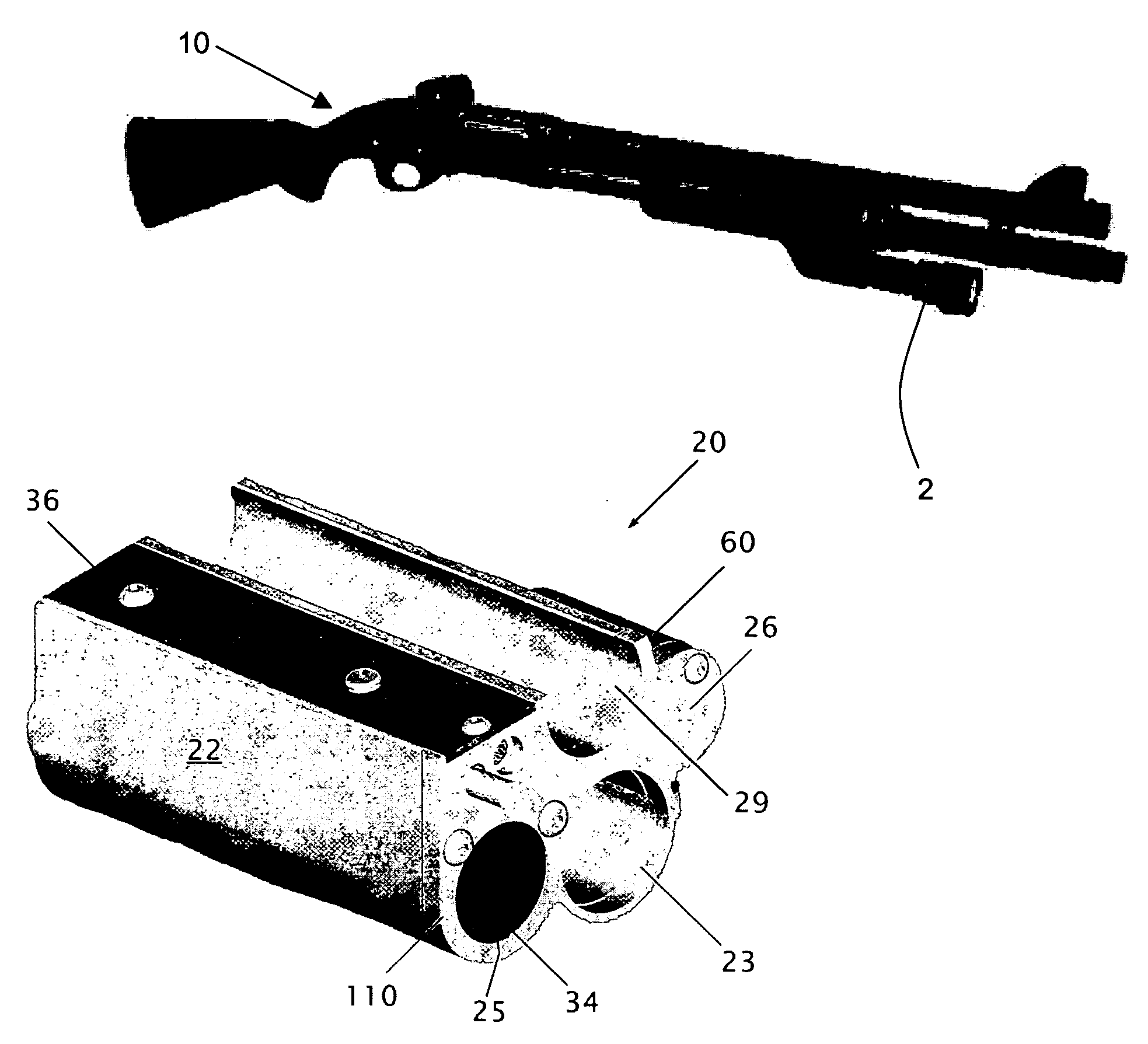
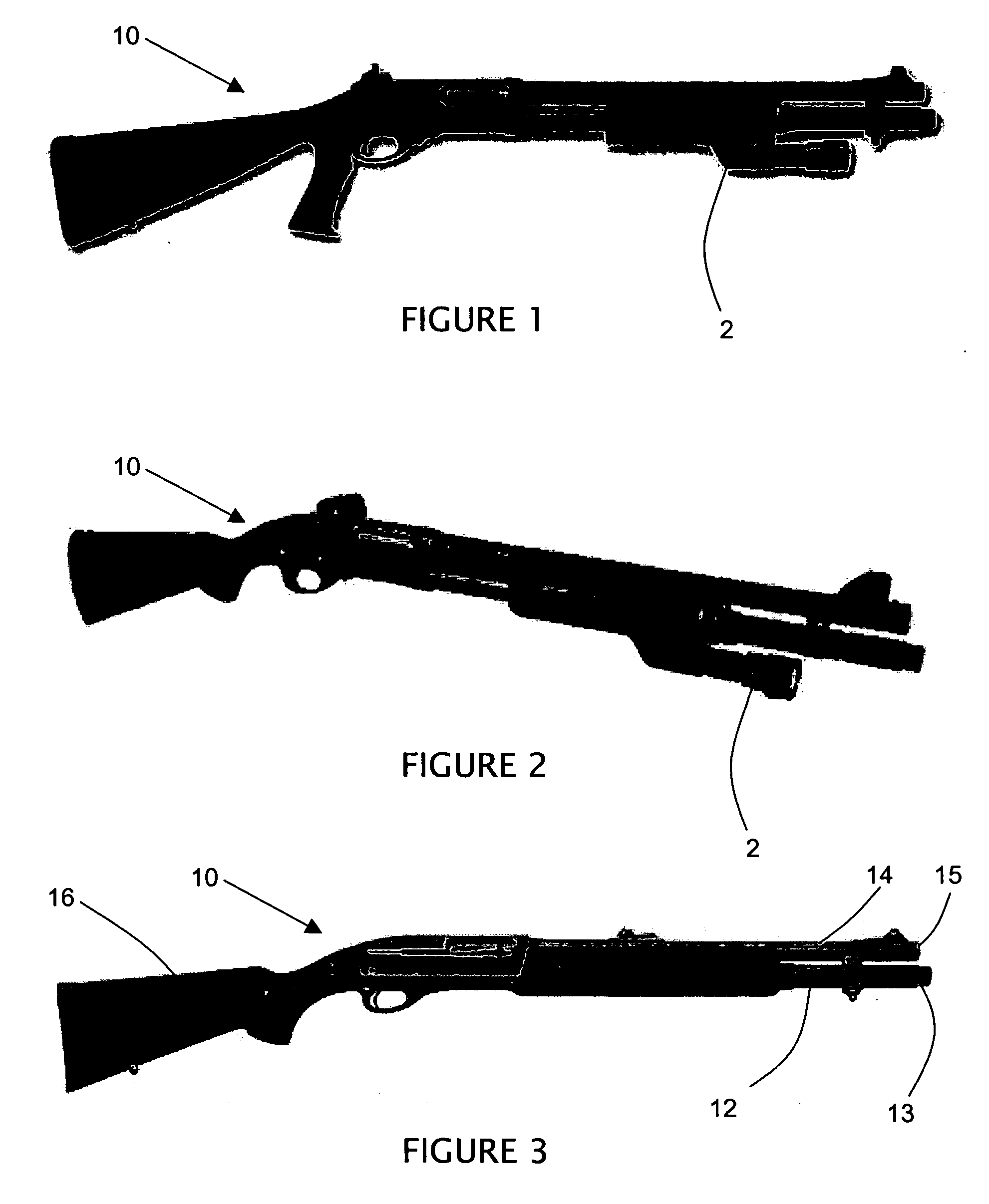
[0037] Referring to FIGS. 1 and 2, a prior art target illuminator 2 is shown connected to a firearm 10.

[0038] The term firearm 10 is intended to encompass any of a variety of firearms, including but not limited to shotguns, rifles, long guns and shoulder guns. In a preferred construction, the firearm 10 includes an elongate barrel and a generally parallel magazine tube.

[0039] The prior art target illuminator 2 connects to a magazine tube and suspends flashlight beneath the magazine tube.

[0040] Referring to FIG. 3, in relevant part the firearm 10 includes a barrel 14, a stock 16 and the magazine tube 12. Typically, the barrel 14 and the magazine tube 12 are generally parallel, wherein the barrel terminates at a forward end 15 and the magazine tube terminates at a corresponding forward end 13 which is slightly spaced from the end of the barrel. The remaining components of the firearm 10 are well known in the art and not included in this description.

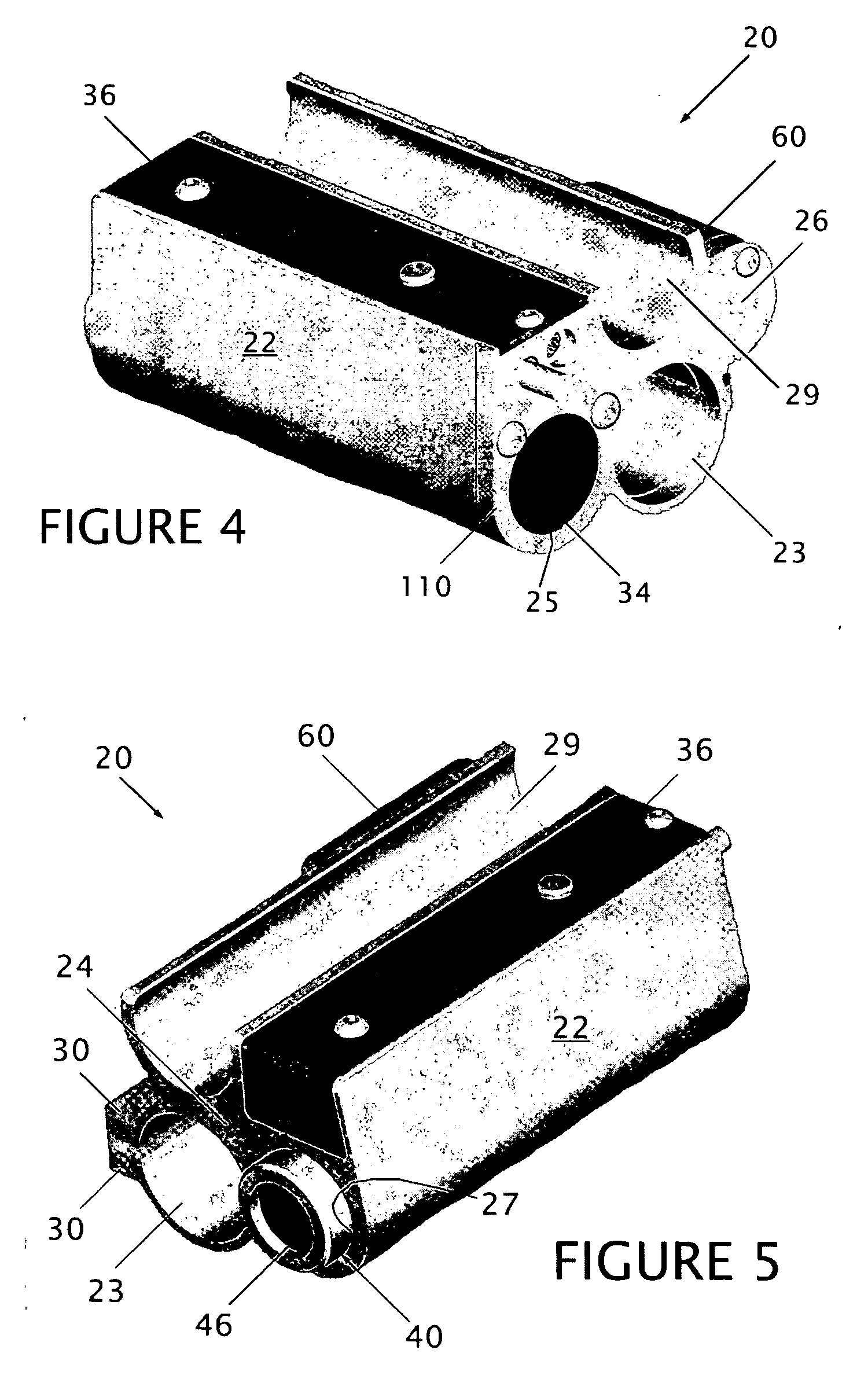
[0041] An integrated magazine tu...


PUM


Abstract

A magazine tube and barrel clamp with integral target illuminator, wherein a laser module can be incorporated is provided for a firearm having a magazine tube and a barrel. The frame defines a clamping sleeve for substantially encircling the magazine tube and a barrel receiving channel for receiving a diameter of the barrel, wherein the magazine tube and the barrel are thus fixed in a predetermined spacing. The frame further defines an illuminator recess for receiving a substantial portion of a reflector in the target illuminator, thereby shielding the target illuminator from contact with external surfaces. A driver circuit is retained within the frame to selectively operate the target illuminator and a laser sight, wherein the target illuminator can be a solid-state light emitting device.

Description

CROSS-REFERENCE TO RELATED APPLICATIONS [0001] Not applicable. STATEMENT REGARDING FEDERALLY SPONSORED RESEARCH OR DEVELOPMENT [0002] Not applicable. REFERENCE TO A “SEQUENCE LISTING”[0003] Not applicable. BACKGROUND OF THE INVENTION [0004] 1. Field of the Invention [0005] The present invention relates to target illuminators and laser sights incorporated into a magazine tube and barrel clamp, wherein an original capacity of the magazine is maintained. [0006] 2. Description of Related Art [0007] Law enforcement and military organizations often find it necessary to perform armed operations in darkness or low-light conditions. To ensure that their mission is carried out properly, successfully and safely, the operational personnel often employ flashlights to illuminate a potential target in the event use of a weapon becomes necessary. However, it is awkward and restrictive to hold a flashlight in one hand and a weapon in the other. Consequently, flashlight attachments to weapons have be...

Claims


Application Information

Patent Timeline
Patent Type & Authority Applications(United States)
IPC IPC(8): F41G1/00
CPCF41G11/001F41G1/35
Inventor KALLIO, ROBERT A.WOLINSKI, JEFFREY S.ALLEN, MICHAEL W.KOLBET, ROBERT J.HOUDE-WALTER, WILLIAM R.
Owner LMD APPL SCI LLC
Why Eureka
Try Eureka