Battery charging system and method

a battery and charging system technology, applied in battery/fuel cell control arrangement, electrochemical generators, transportation and packaging, etc., can solve the problems of increasing the current carried by the system circuit breaker, needing to be upgraded, and large capital expenditures, so as to reduce the cost per charger, prevent the need for additional capital expenditures, and maximize the return on capital investment

Inactive Publication Date: 2007-08-14
WEBASTO CHARGING SYST INC
View PDF15 Cites 247 Cited by
  • Summary
  • Abstract
  • Description
  • Claims
  • Application Information

AI Technical Summary

Benefits of technology

[0016]An advantage of at least some embodiments of the invention is that the utility power requirements of the charging system on a facility's electrical system are managed by the power management controller to meet the facility's overall electrical system requirements by managing the load allocated to each of the charging systems' connection ports. By varying the power allocation in a logical fashion, multiple charging requirements can be met while meeting the utility power requirements.
[0017]Another advantage of at least some embodiments of the invention is that, by design, the system will be capable of simultaneous or parallel charging. This allows for various levels of charging to simultaneously occur, such as equalizing occurring on one battery while fast-charging is occurring on another. Since multiple vehicles are allowed to charge at different rates at the same time and from the same utility connection, the utility can be utilized to maximize the return on capital investment or even to prevent requiring further capital expenditures.
[0018]Yet another advantage of at least some embodiments of the invention is that they provide for selectively parallel operation of individual charging systems (e.g., individual power converters). In particular, the embodiments' internal circuitry includes switching connections such that the amount of output power to a battery can be greater than one of the charging system's power converters would normally be capable. This allows for chargers having a capacity lower than the maximum needed capacity, which lowers the cost per charger. This feature can be extended to cover a large number of power processing circuits, which could be assigned at will to an individual port to match any given power allocation strategy.
[0019]Furthermore, if power ports of the present invention are designed to be capable of both charging or discha

Problems solved by technology

The implementation of such charging systems in existing facilities' electrical systems (e.g., building electrical systems) presents significant problems that can lead to large capital expenditures, as described below.
Upgrading such a charging system to charge greater numbers of vehicles (or installing a battery charging system where none is in place) can significantly increase the current carried by the system circuit breaker, and therefore it will likely need to be upgraded to carry additional current.
Thus, increasing the number of vehicles that can be charged can potentially require expensive upgrading of a substantial portion of the facility's electrical system, requiring significant capital expenditures.
This is required even though the individual chargers might not all be in use at the same time and, if they are in use, they will most likely not be simultaneously operating at full power and fully utilizing the existing infrastructure.
Thus, the capital expense of adding vehicle chargers to a system potentially includes the significant costs of upgrading a significant portion of the entire electrical system.
Furthermore, the batteries in each vehicle will likely have different charging requirements.
While the chargers can be configured to handle either load level, the capacity of the charger used on vehicle #1 will be wasted even though the facility's enti

Method used


Image

  • Battery charging system and method
  • Battery charging system and method
  • Battery charging system and method

Examples


first embodiment

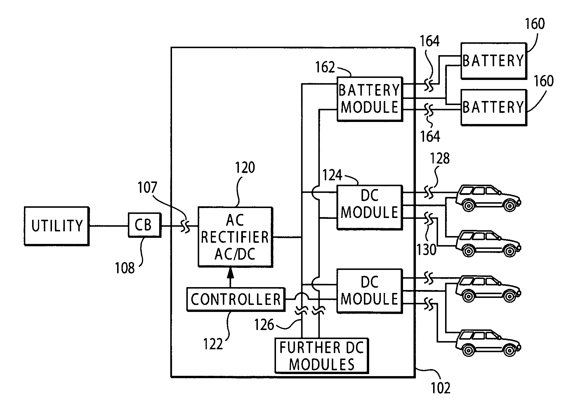
[0030]an electrical power distribution system according to the present invention is a vehicle charging system 100 shown in FIG. 3A. The charging system includes a system controller, a power processor 102 and a series of one or more (and preferably a plurality of) secondary power ports 104 that are configured for connecting to the batteries of one or more vehicles 106 (i.e., to loads placed on the distribution system). Each secondary power port has a power rating, which is preferably adequate to meet the charging needs of vehicles that will be charged via that secondary power port. The sum of the secondary power ports' power ratings defines an aggregate output power rating.

[0031]The charging system 100 preferably receives power from a power system, e.g., a utility having an AC electrical system. This power is received by a primary power port 107A, which in turn provides the power to the power processor. The power is received by the primary power port through a circuit breaker 108A th...


PUM


Abstract

A charging system for simultaneously charging the batteries of a plurality of battery powered vehicles. The charging includes one or more DC-DC power converters having one or more charging ports configured to plug into the batteries. The DC-DC power converters are each configured to selectively connect to more than one charging port to selectively provide for higher port power levels. The DC-DC power converters connect to an AC rectifier through a DC bus. The AC rectifier connects to an AC power source having a limited power rating. The AC charging system also has a controller that controls the operation of the DC-DC power converters such that the total power draw on the AC rectifier does not exceed the power rating. The system is further configured such that the DC-DC power converters can drain selected batteries to obtain power for charging other batteries, thus allowing for batteries to be cycled.

Description

BACKGROUND[0001]The present application is a continuation-in-part of application Ser. No. 09 / 881,561, filed Jun. 14, 2001 now abandoned, which claims priority from Provisional Application Ser. No. 60 / 212,066, filed Jun. 14, 2000, both of which are incorporated herein by reference for all purposes.[0002]This invention relates generally to battery charging systems and methods for charging batteries and, more particularly, to a cost-efficient charging system and method for simultaneously charging the batteries of a plurality of electrically powered vehicles such as forklifts.[0003]Increasing numbers of vehicles (e.g., forklifts) are being manufactured as electric vehicles. Vehicle charging systems for the batteries of larger numbers of vehicles, such as for a fleet of forklifts vehicles, are therefor increasingly important. The implementation of such charging systems in existing facilities' electrical systems (e.g., building electrical systems) presents significant problems that can le...

Claims


Application Information

Patent Timeline
IPC IPC(8): H02J7/04B60L11/18B60R16/02B60R16/03H02J1/14H02J7/00
CPCB60L11/1811B60L11/1838B60L11/1842B60L11/1846B60L11/185B60L11/1851H01M10/441H02J1/14H02J7/0027B60L11/1824Y02T90/121B60L2210/20B60R16/03Y02E60/721Y02T10/7005Y02T10/7055Y02T10/725Y02T10/92Y02T90/127Y02T90/128Y02T90/14Y02T90/169Y04S10/126Y04S30/14Y02T10/705B60L53/14B60L53/20B60L55/00B60L53/63B60L53/65B60L53/11B60L58/10B60L53/53H02J2310/46B60L53/67Y02E60/00Y02T10/72Y02E60/10H02J7/0013Y02T90/167Y02T10/70Y02T10/7072Y02T90/12
Inventor BUCHANAN, WILLIAM D.MOHOS, JOSEPH F.RIPPEL, WALLY E.
Owner WEBASTO CHARGING SYST INC
Why Eureka
Try Eureka