
Automotive Radar System

A technology for radar systems and vehicles, applied in radio wave measurement systems, using re-radiation, instruments, etc., can solve problems such as increasing complexity and increasing production costs, and achieve the effect of reducing production costs

Active Publication Date: 2021-03-16
WISTRON NEWEB
View PDF7 Cites 0 Cited by
  • Summary
  • Abstract
  • Description
  • Claims
  • Application Information

AI Technical Summary

Problems solved by technology

However, the known technology has not developed a radar antenna system that can simultaneously achieve the four different functions of the LCA system, the DOW system, the RCTA system and the BSD system, so the known technology needs to separate each side of the vehicle (left rear side or right rear side) Install multiple sets of different radar antenna systems, where the radiation pattern of one set of radar antenna systems faces the rear of the vehicle for use by the LCA system or DOW system, while the radiation pattern of the other set of radar antenna systems faces the side of the vehicle, For RCTA system or BSD system use
In this case, installing multiple sets of radar antenna systems not only increases production costs, but also increases the complexity of system integration

Method used


Image

  • Automotive Radar System
  • Automotive Radar System
  • Automotive Radar System

Examples


Embodiment Construction

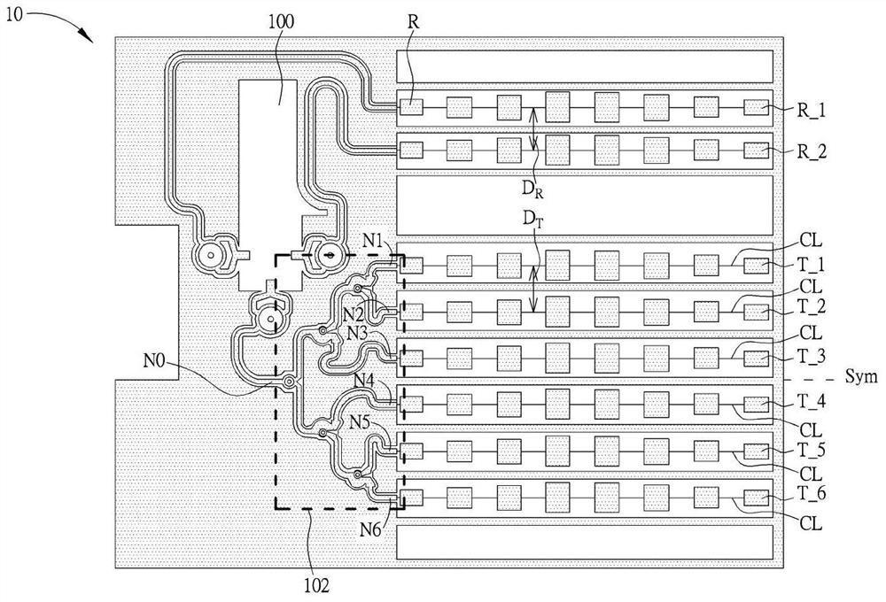
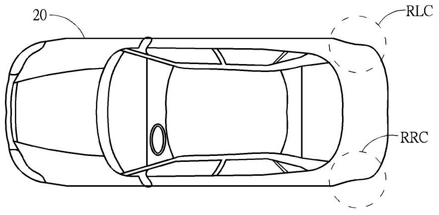
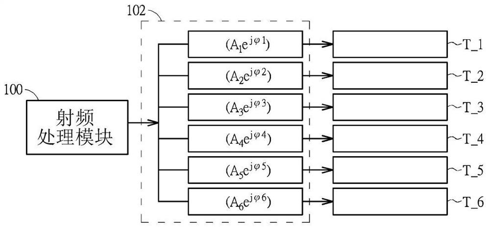
[0034] Please refer to figure 1 and figure 2 , figure 1 It is a schematic diagram of a vehicle radar system 10 according to an embodiment of the present invention, figure 2 is a schematic diagram of a vehicle 20 . The vehicle radar system 10 can be simultaneously applied to a Lane Change Assistance (Lane Change Assistance, LCA) system, a Door Open Warning (Door Open Warning, DOW) system, a rear side traffic warning (RearCross Traffic Alert, RCTA) system and A blind spot detection (Blind Spot Detection, BSD) system, the vehicle radar system 10 can be arranged at the corners on both sides of a rear bumper of the vehicle 20, such as figure 2 As shown, the vehicle radar system 10 can be installed at a left rear corner RLC or a right rear corner RRC of the vehicle 20 . In order to achieve a better early warning and protection effect, two sets of vehicle radar systems 10 can be respectively arranged on both sides of the vehicle 20 (that is, only one set of vehicle radar syste...


PUM


Abstract

A vehicle radar system includes a plurality of transmission sub-arrays, wherein the plurality of transmission sub-arrays are symmetrical with respect to a symmetry axis and the plurality of transmission sub-arrays are parallel to the symmetry axis. The vehicle radar system further includes a transmission power splitter which is coupled to the plurality of transmission sub-arrays for respectively applying a plurality of phases and a plurality of amplitudes corresponding to the plurality of transmission sub-arrays to the plurality of transmission sub-arrays; wherein among the plurality of transmission sub-arrays, a first transmission sub-array which is closest to the symmetry axis and a second transmission sub-array which is farthest from the symmetry axis have a phase difference between 120 degrees and 180 degrees. The vehicle radar system of the present invention can simultaneously meet the system requirements of the LCA system, the DOW system, the RCTA system and the BSD system, thereby reducing the production cost and the complexity in system integration.

Description

technical field [0001] The invention relates to a vehicle radar system, in particular to a vehicle radar system capable of simultaneously detecting vehicles coming from the rear and sides of the vehicle. Background technique [0002] With the enhancement of traffic safety awareness, vehicle safety equipment is becoming more and more diversified. In addition to active and passive safety systems (such as anti-deadlock braking system, braking force distribution system, tracking system, electronic stability system, auxiliary airbag, etc.), early warning The protection system has also gradually received attention. The early warning and protection system detects the traffic conditions behind or on the side of the vehicle through the radar system, and then actively sends out warning lights or warning sounds and other information to the driver, so that the driver can determine the driving direction according to the warning results, thereby avoiding traffic accidents. . [0003] Co...

Claims


Application Information

Patent Timeline
Patent Type & Authority Patents(China)
IPC IPC(8): G01S13/931G01S7/03
CPCG01S7/03G01S13/931G01S2013/9315G01S2013/93272
Inventor 黄国书
Owner WISTRON NEWEB
Learn More