Micro-controller control system and control method thereof

A microcontroller and control system technology, applied in the direction of output power conversion devices, electrical components, etc., can solve the problems of unsuitable control systems, etc., and achieve the effects of improving accuracy and anti-interference, convenient debugging, and stable and reliable control

Inactive Publication Date: 2018-03-09
HANGZHOU GAOPIN AUTOMATION EQUIP
View PDF3 Cites 0 Cited by
  • Summary
  • Abstract
  • Description
  • Claims
  • Application Information

AI Technical Summary

Problems solved by technology

Although this invention is used for the drive of the electromagnetic valve in the internal combustion engine fuel injection system, it cannot be applied to the control system of this application

Method used


Image

  • Micro-controller control system and control method thereof

Examples


Embodiment Construction

[0020] The present invention will be further described in detail below in conjunction with the accompanying drawings and examples. The following examples are explanations of the present invention and the present invention is not limited to the following examples.

[0021] Example.

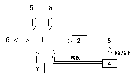
[0022] see figure 1 , the microcontroller control system of this embodiment includes an MCU microcontroller 1, a driver chip 2, a power module 3, a current detection circuit 4, a power module 5 and a communication conversion module 6, and the MCU microcontroller 1 supplies power through the power module 5, and the communication The conversion module 6 is connected with the MCU microcontroller 1 , the driver chip 2 is connected with the power module 3 , the driver chip 2 is connected with the MCU microcontroller 1 , and the current detection circuit 4 is matched with the power module 3 .

[0023] Both the clock source 7 and the watchdog module 8 in this embodiment are connected to the MCU microcont...


PUM


Abstract

The invention relates to an electromagnetic valve driver control system and a control method thereof, and belongs to the field of controller controlling. The microcontroller control system comprises apower supply module, a MCU, a communication conversion module, a drive chip, a power module and a current detection circuit, wherein the power supply module is used for supplying power to the MCU; the communication conversion module is communicated with the MCU; the drive chip is connected with the power module; the drive chip is connected with the MCU; and the current detection circuit is matched with the power module. The invention further provides a method for controlling the microcontroller. The microcontroller control system is reasonable in design, is stable and reliable, use of a traditional simulating device is reduced, the digital level of the system is improved, debugging is convenient, and accuracy and interference resistance of the system are improved.

Description

technical field [0001] The invention relates to a control and its method, in particular to a micro-controller control system and its control method, belonging to the field of controller control. Background technique [0002] In the solenoid valve driver control system, the design of the solenoid valve driver circuit is a key part of the whole control system. In the past, the drive circuit design was generally based on analog circuits, and the drive control of the solenoid valve was completed through operational amplifier circuits, PWM wave drive circuits, and current and voltage sampling circuits. Such designs are susceptible to external interference in industrial environments, and the drive system The debugging process is cumbersome and the accuracy is not high. [0003] The publication date is March 13, 2013, and the Chinese patent with the publication number 102966452A discloses an invention patent named "solenoid valve driving method and device". The patent includes th...

Claims


Application Information

Patent Timeline
Patent Type & Authority Applications(China)
IPC IPC(8): H02M1/08
CPCH02M1/08
Inventor 张志刚赵志龙徐顺士
Owner HANGZHOU GAOPIN AUTOMATION EQUIP
Why Eureka
Try Eureka