
Device and method for dark field illumination

a technology of dark field illumination and apparatus, which is applied in the direction of microscopes, instruments, printing, etc., can solve the problems of reducing the working distance, reducing the illumination effect,

Inactive Publication Date: 2001-07-10
NIKON CORP
View PDF7 Cites 36 Cited by
  • Summary
  • Abstract
  • Description
  • Claims
  • Application Information

AI Technical Summary

Benefits of technology

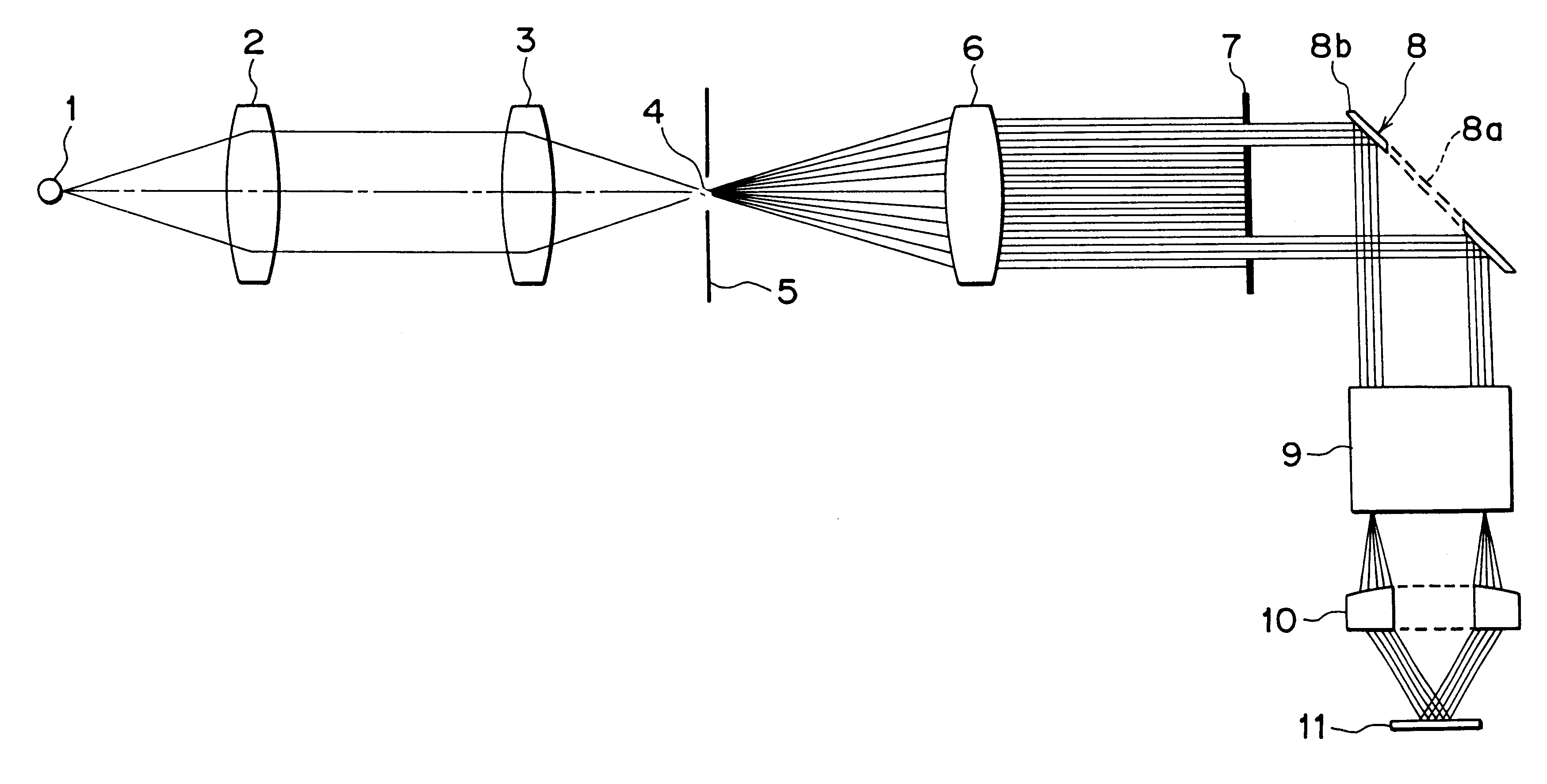
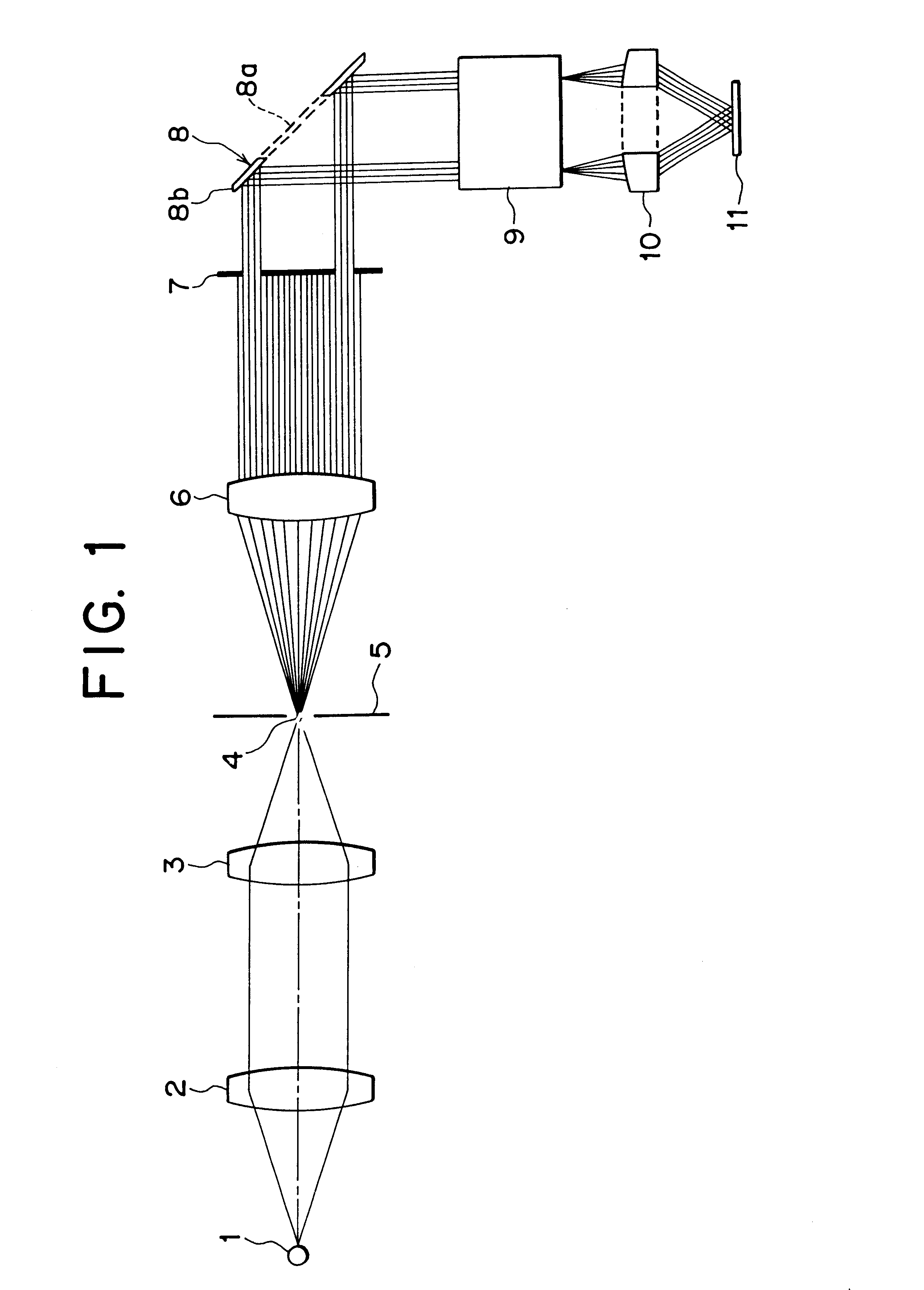
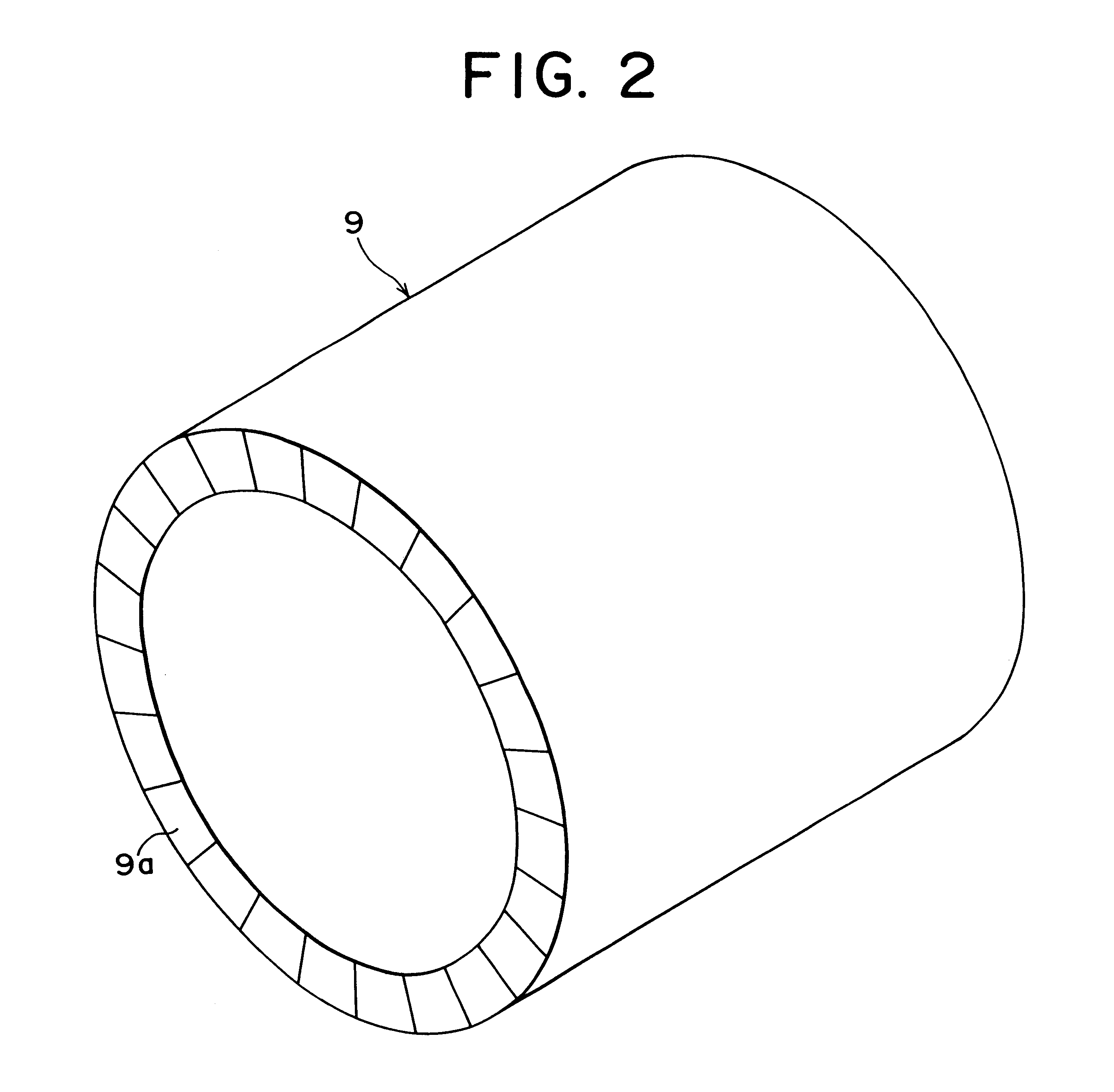
In the foregoing apparatus, the illumination light from the light source is shaped to the approximately parallel light beam having the ring-shaped section, and then the approximately parallel beam is incident onto the optical integrator composed of the plurality of elements. The approximately parallel beam which is incident onto a ring-shaped incidence plane of the optical integrator forms the plurality of light source images arranged circularly on the predetermined plane. The light beams from the plurality of light source images formed so as to be arranged circularly are collected by the light collection optical system, and then superimposed on the object. In this case, the illumination light performs a Koehler illumination or an illumination akin to the Koehler illumination for the object plane so as to be superposed, so that an illuminated field in which unevenness in brightness is sufficiently suppressed is formed. Moreover, unlike a case where a light beam is diffused using a diffuser or the like in prior arts, the light beam incident onto a fly-eye element does not lose substantially its quantity of light and guided into the object plane through the light collection optical system. As a result, the illuminated field having a sufficient brightness is formed.
Furthermore, if aberration is left in the light collection optical system to some extent, the conversion of the light beams from the plurality of light source images to the parallel beam becomes impossible. As a result, an illuminated field having somewhat unevenness in brightness is formed on the object plane. Accordingly, in the case where a ring-shaped lens component is used as the light collection optical system, it should be preferable that the light collection optical system has less aberration as possible by introducing an aspheric surface into at least one plane of the lens component. Alternatively, instead of a refraction system like the lens component, it should be preferable to further suppress the unevenness in brightness in the illuminated field by using a ring-shaped parabolic concave reflection mirror as the light collection optical system which has in principle no aberration.

Problems solved by technology

In other words, a part of the light diffused by the diffuser does not contribute to the illumination, thus causing a loss of a quantity of light.
As a result, the part of the light passing through the condenser lens is obstructed by the fixed diaphragm and lost without contributing to the illumination.
At the same time, a working distance is shortened by the disposition of the fixed diaphragm, and an operability is deteriorated.
As described above, in the conventional dark field illumination apparatus, there has been a disadvantage that a sufficient brightness cannot be obtained in an illuminated field of the object due to a loss of a quantity of light created by the diffuser or the fixed diaphragm.
Moreover, since the conventional dark field illumination apparatus does not adopt an optical arrangement for Koehler illumination, there has been a disadvantage that evenness in brightness exists in a wide visual field to be observed particularly at the time of using a low magnification microscope object lens.
As a result, unevenness in brightness occurs in the illuminated field owing to the non-telecentric light beam.
Accordingly, when the fly-eye optical device formed of the large number of single lenses is made of plastic and the like by a pressing work for the single lenses so as to integrate them to one constituent component, an error in manufacturing is more apt to occur as a thickness of the fly-eye optical device is larger.
If the fly-eye optical device and the light collection optical system are disposed within a microscope main body, a good illumination itself not only tends to be impossible, but also the tester is urged to perform an excessive operation every time of switching the object lens, thus significantly deteriorating the operability.
Furthermore, if aberration is left in the light collection optical system to some extent, the conversion of the light beams from the plurality of light source images to the parallel beam becomes impossible.
In this case, if the condenser lens 10 holds aberration left therein to some extent, it will be impossible to convert the light beams from many light source images to the parallel light beam.

Method used


Image

  • Device and method for dark field illumination
  • Device and method for dark field illumination
  • Device and method for dark field illumination

Examples


second numerical example

A second numerical example concerns an apparatus which performs a dark field illumination for a tenfold object lens of a microscope, that is, an intermediate magnification object lens, and the apparatus uses a condenser lens as the light collection optical system based on the constitution of the foregoing embodiment in the apparatus. Similarly to the apparatus in the first numerical example, this condenser lens is a ring-shaped biconvex lens, and a lens surface on the light source side is formed to be aspheric. However, dimensions of the numerical values in the second numerical example differ from those in the first numerical example.

Specific values of a fly-eye optical device and a condenser lens in the second numerical example are listed in the following Table 2. Note that a refractive index shows a value for a d line (.lambda.=587.6 nm).

FIG. 9 is a graph showing an intensity distribution of an illuminated field formed on an object plane in the second numerical example. In FIG. 9,...

third numerical example

A third numerical example concerns an apparatus which performs a dark field illumination for a microscope object lens having a twenty-fold magnification, that is, a high magnification object lens, and the apparatus uses a parabola concave reflection mirror as the light collection optical system based on the foregoing first modification example. A parabola plane of the parabola concave reflection mirror is represented by the following formula (b) when y is a height in a direction perpendicular to the optical axis, x is a distance along the optical axis from a tangent plane at a vertex of an parabola plane to the parabola plane in the height y, and .kappa. is a conic constant.

x=(A.multidot.y.sup.2) / [1+{1-(1+.kappa.)A.sup.2.multidot.y.sup.2 }.sup.1 / 2 ] (b)

where a coefficient A is 1 / R

(R: curvature radius of vertex)

Specific values of the fly-eye optical device and the parabola concave reflection mirror in the third numerical example are listed in the following Table 3. Note that a refrac...


PUM


Abstract

Disclosed is a dark field illumination apparatus which is capable of performing a dark field illumination which exhibits a sufficient brightness and a sufficiently suppressed unevenness in brightness. The apparatus comprises a shaping system for shaping a light beam from a light source into approximately parallel beam having a ring- shaped section; a fly-eye optical device for forming a plurality of light source images in the vicinity of its exit plane based on the approximately parallel beam, the light source images being arranged circularly; and a light collection optical system for collecting light beams from the light source images and superposing them on an object plane.

Description

This application claims the benefit of Japanese Application No. 11-115647 which is hereby incorporated by reference.1. Field of the InventionThe present invention relates to a dark field illumination apparatus and a dark field illumination method more particularly to an epi-illumination type of dark field illumination for an object to be observed in a microscope.2. Related Background of the InventionIn semiconductor device manufacturing steps, to inspect dusts, flaws and the like on a wafer that is a photosensitive substrate, a microscope observation using a dark field illumination has been often used. In the microscopic observation using the dark field illumination, areflection light from an object to be observed and a transmission light therefrom are not directly observed, but a scattered light from the object is observed. In the case where the object to be observed is a wafer and the like, the object can be observed with a better contrast in a dark field illumination than in a br...

Claims


Application Information

Patent Timeline
IPC IPC(8): G02B21/06G02B21/10G02B3/00G02B5/00
CPCG02B3/00G02B21/10G02B5/001
Inventor MIYASHITA, TOMOHIROSUENAGA, YUTAKA
Owner NIKON CORP
Learn More