Zoom lens, camera, and portable information terminal device

a technology of information terminal device and zoom lens, which is applied in the field of zoom lens, camera and portable information terminal device, can solve the problems of increasing noise, complicated exposure control during monitoring using display elements, and gradual darkening of monitor images, and achieves the effect of significantly increasing the degree of freedom in correction of aberration

Inactive Publication Date: 2005-01-04
RICOH KK
View PDF18 Cites 40 Cited by
  • Summary
  • Abstract
  • Description
  • Claims
  • Application Information

AI Technical Summary

Benefits of technology

The thus provided aspherical surfaces primarily contribute to correction of spherical aberration or frame aberration. On the other hand, since the surface proximate to the image side of the second optical system is distant from the aperture stop, the light fluxes on and outside the axis pass with being separated from each other to some extent. The thus provided spherical surfaces contribute to correction of frame aberration and non-spherical aberration. In this way, the two aspherical surfaces are used for the surface proximate to the object side or the surface proximate to the image side, whereby the respective aspherical surfaces bring sufficiently different effect, and the degree of freedom in correction of aberration significantly increases.

Problems solved by technology

This is because of the absence of sufficient brightness at the telephoto end delays a shutter speed at the telephoto end, and causes a motion of hands or a motion of an object.
On the other hand, if such insufficient brightness is compensated for by an increase of gain of an imaging device, it causes higher noise.
In addition, there is another problem that, if there is a significant change of brightness in accordance with zooming from a wide-angle end to a telephoto end, exposure control during monitoring using a display element becomes complicated.
However, in the case where a lens is darkened at the telephoto end, if no exposure control is carried out while in zooming, a monitor image is gradually darkened.
However, all of the zoom lenses disclosed as embodiments or specific examples in the above described JP-L Nos. 10-39214, 11-287953, and 2001-296476 have a disadvantage that they cannot acquire sufficient brightness at a telephoto end, and include a significant change of brightness in accordance with zooming from the wide-angle end to the telephoto end.

Method used


Image

  • Zoom lens, camera, and portable information terminal device
  • Zoom lens, camera, and portable information terminal device
  • Zoom lens, camera, and portable information terminal device

Examples


first embodiment

(First Embodiment)

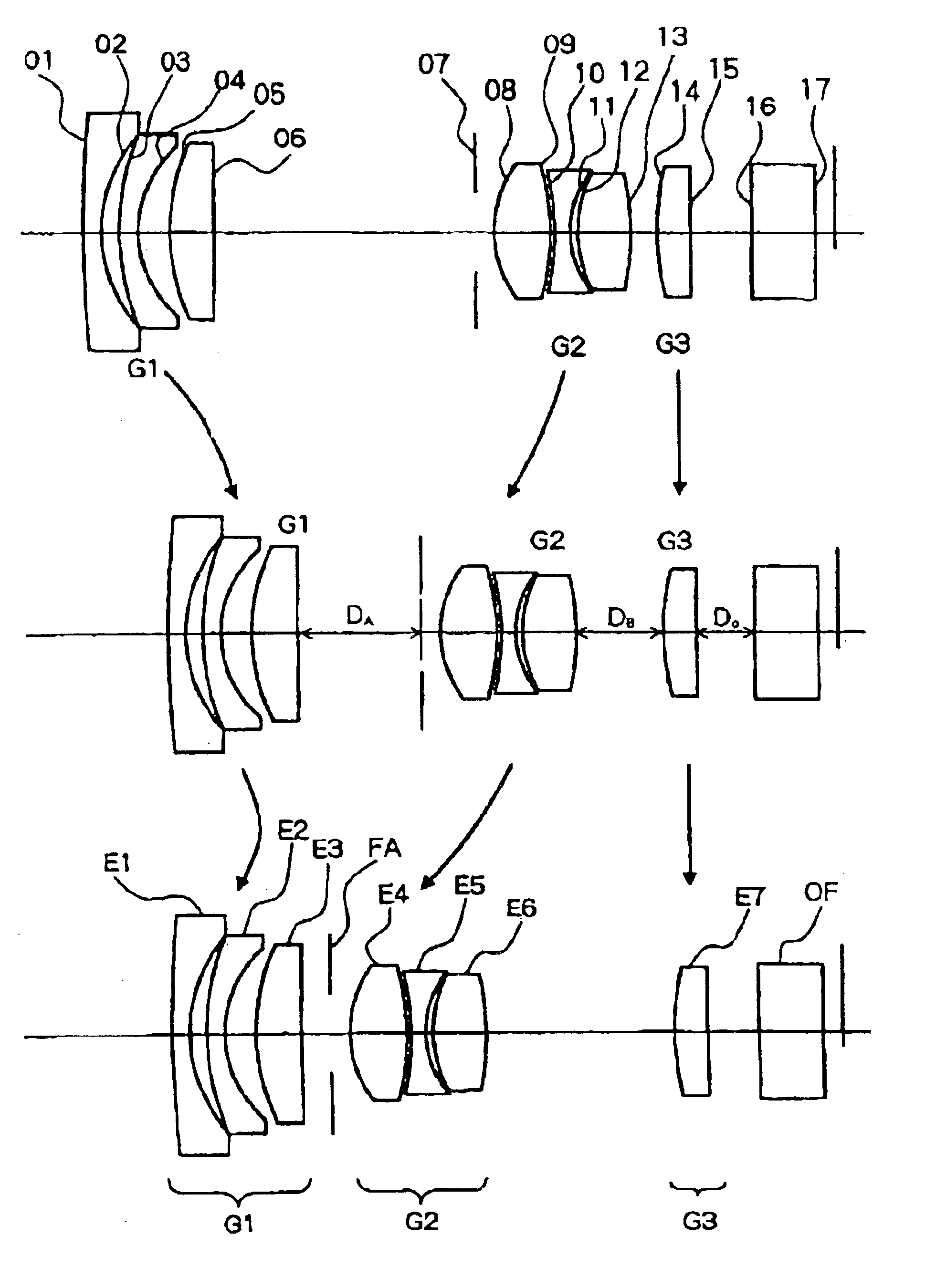
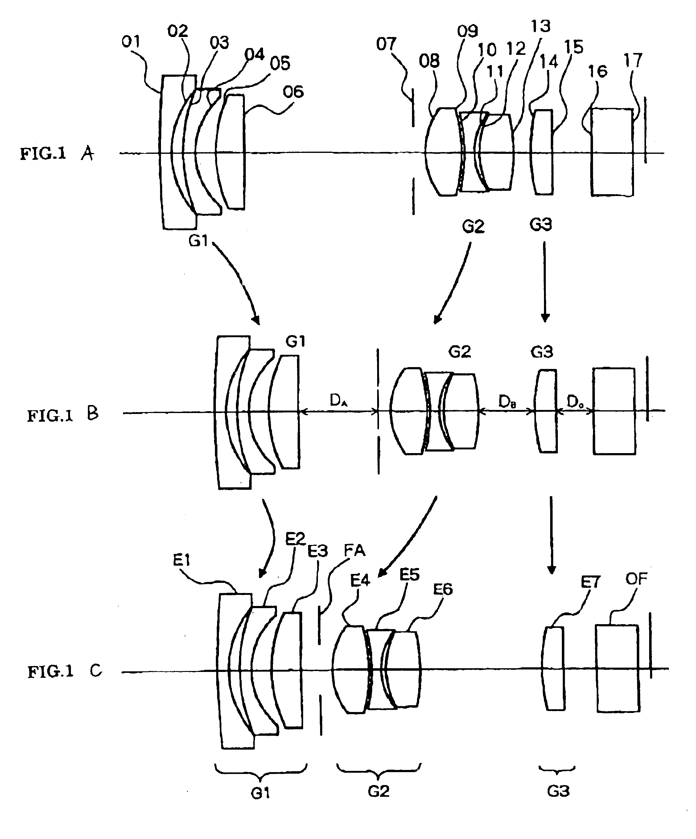
FIGS. 1A to 1C show a configuration of an optical system of the zoom lens according to the first embodiment of the present invention. In order to grasp a zooming operation, FIG. 1A is a sectional view schematically showing a state of a short focal length end which is a wide angle end; FIG. 1B is a sectional view schematically showing a state of a middle focal length; and FIG. 1C is a sectional view taken along an optical axis schematically showing a state of a long focal length end which is a telephoto end, respectively.

A zoom lens shown in FIG. 1 comprises a first lens E1, a second lens E2, a third lens E3, a fourth lens E4, a fifth lens E5, a sixth lens E6, a seventh lens E7, a aperture stop lens E3, and an optical filter OF. In this case, the first lens E1 to third lens E3 configure a first group optical system G1; the fourth lens E4 to sixth lens E6 configure a second group optical system E2; and the seventh lens E7 configures a third group optical system G3. E...

second embodiment

(Second Embodiment)

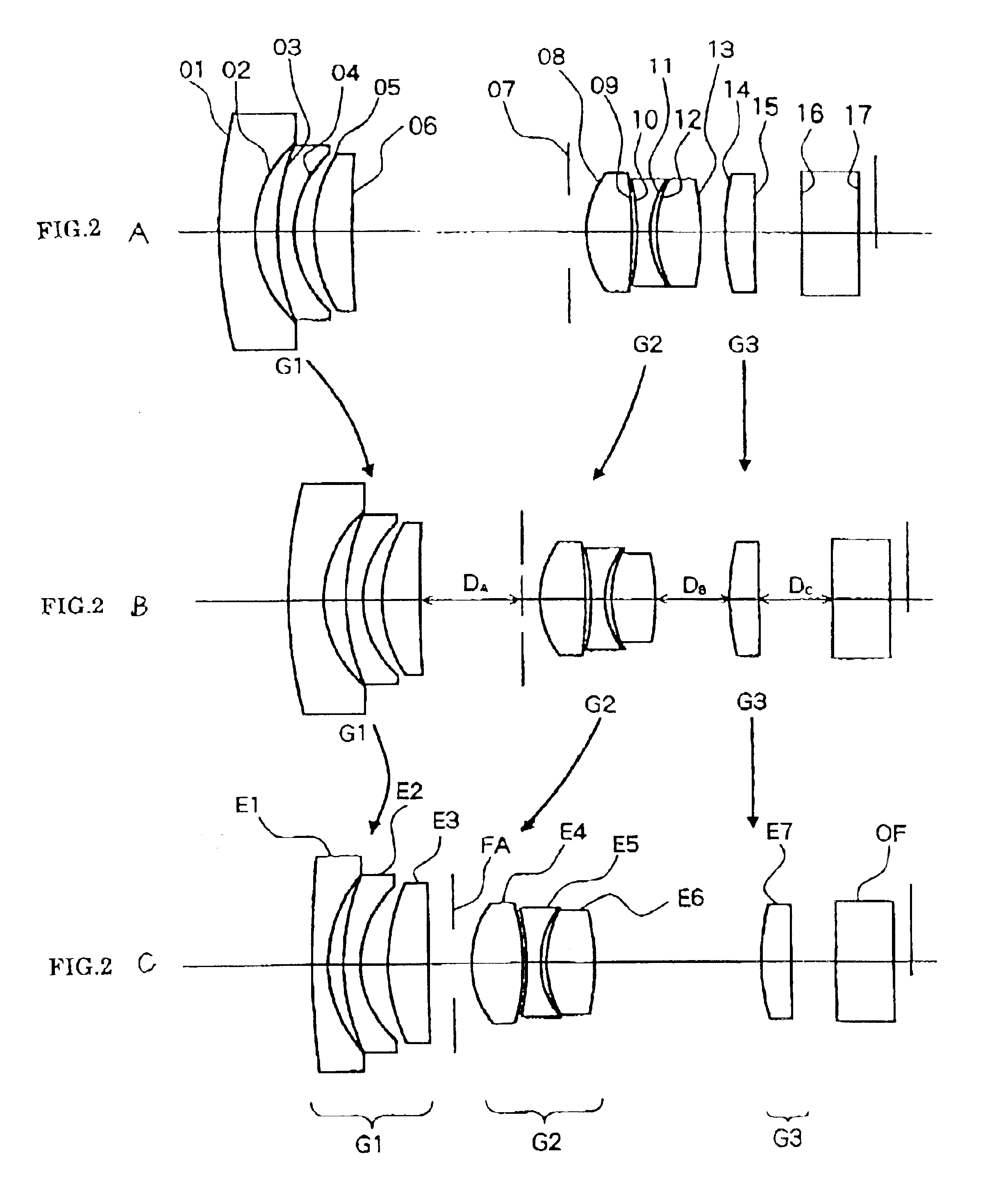
FIGS. 2A to 2C show a construction of an optical system of the zoom lens according to the second embodiment of the present invention. In order to grasp a zooming operation, FIG. 2A is a sectional view taken along an optical axis, for schematically showing a short focal length end which is a wide angle end; FIG. 2B is a sectional view schematically showing a state of a middle focal length; and FIG. 2C is a sectional view taken along an optical axis, for schematically showing a state of a long focal length end which is a telephoto end, respectively.

A zoom lens shown in FIG. 2 comprises a first lens E1, a second lens E2, a third lens E3, a fourth lens E4, a fifth lens E5, a sixth lens E6, a seventh lens E7, a aperture stop FA, and an optical filter OF. In this case, the first lens E1 to third lens E3 configure a first group optical system G1; the fourth lens E4 to sixth lens E6 configure a second group optical system G2; and the seventh lens E7 configures a third gro...

third embodiment

(Third Embodiment)

A zoom lens shown in FIG. 3 comprises a first lens E1, a second lens E2, a third lens E3, a fourth lens E4, a fifth lens E5, a sixth lens E6, a seventh lens E7, an eighth lens E8, a aperture stop FA, and an optical filter OF. In this case, the first lens E1 to third lens E3 configure a first group optical system G1; the fourth lens E4 to seventh lens E7 configure a second group optical system G2; and the eighth lens E8 configures a third group optical system G3. In the Figure, optical surfaces are designated by numbers of their corresponding face. As described above, reference numerals in FIG. 3 are used independently of another embodiment.

In FIG. 3 as well, for example, the first lens E1, second lens E2, third lend E3, aperture stop FA, fourth lens E4, fifth lens E5, sixth lens E6, seventh lens E7, eighth lens E8 and optical filter OF are sequentially arranged in this order from an object side of an object or the like, and an image is formed at the rear of the opt...


PUM


Abstract

A zoom lens includes a negative first group optical system, and a positive second group optical system, which are sequentially arranged from an object side, and an aperture stop disposed on the object side of the second group optical system moving integrally therewith. During change of magnification from a short focal end to a long focal end, the second group optical system monotonously moves from the image side to the object side, and the first group optical system moves so as to correct displacement of an image plane position in accordance with the change of magnification.

Description

BACKGROUND OF THE INVENTION1. Field of the InventionThe present invention relates to improvement in a zoom lens used as a photography optical system for a variety of cameras including a so-called silver camera, and more particularly, to a zoom lens suitable for cameras such as a digital camera and a video camera, and a camera and a portable information terminal device using such a zoom lens.2. Description of the Prior ArtIn recent years, instead of a conventional camera using a silver film, i.e., a sliver camera, there has been rapidly known a camera of such type referred to as a digital camera, an electronic camera or the like, which photographs an image of a subject (object) by a solid-state imaging device such as a CCD (charge coupled device), thereby acquiring image data such as a static image (still image) or a motion image (movie image) of the object and digitally recording the data in a nonvolatile semiconductor memory represented by a flash memory.A market for such a digital...

Claims


Application Information

Patent Timeline
Patent Type & Authority Patents(United States)
IPC IPC(8): G02B15/177G02B13/18G02B15/20H04N5/225
CPCG02B15/177G02B15/143507
Inventor OHASHI, KAZUYASU
Owner RICOH KK
Why Eureka
Try Eureka