Instrument rack with direct exhaustion

a technology of instrument racks and exhaustion pipes, applied in the field of racks, can solve the problems of affecting the appearance, and affecting the service life of the electronic componen

Active Publication Date: 2007-02-27
ADVANTEST CORP
View PDF26 Cites 133 Cited by
  • Summary
  • Abstract
  • Description
  • Claims
  • Application Information

AI Technical Summary

Benefits of technology

[0034]It should be noted that by means of the present invention, support columns and angles are used in addition to side covers and panels in order to form the air duct, but the effect of controlling the exhaust air that passes through the inside of the air duct is relatively small when compared to the side covers and panels, and embodiments wherein this effect can be all but disregarded are also possible. In this sense, the phrase “the side covers and panels substantially form the air ducts” is used.

Problems solved by technology

Many diverse electronic devices: personal computers, measuring instruments and others have been installed in places ranging from business offices to factories in recent years, and the environmental conditions under which each electronic device is used have become critical as a result.
Electronic devices for this type of rack mount are generally equipped with fans that cool each electronic device because when the temperature of each electronic component in the device housing increases too much due to the emission of heat, problems occur in that degradation of the electronic component takes place, and further, its service life is curtailed.
Nevertheless, this type of rack is awkward to look at, foreign matter easily enters the inside of the rack, and the heat generated is uncomfortable to users of equipment near the rack.
Moreover, when several racks of this type are lined up close to one another, heat is exchanged between the adjacent racks and this leads to an abnormal increase in temperature of the mounted electronic devices.
Nevertheless, there are problems with this method in that the rise of air as a result of natural convection is weak and the amount of air that can be discharged to outside the rack is insufficient.
In addition, the convection of air is disturbed by agitation of the air inside the rack by the fans of the electronic devices and this also reduces heat discharge efficiency.
Furthermore, there is a problem in that if electronic devices that reach a high temperature are placed at the bottom of the rack, the electronic devices at the top inside the rack will be exposed to air that is hotter and therefore, placement of the electronic devices is difficult.
By means of this method, the amount of heat that can be discharged increases in proportion to the capability of the additional fans, but electricity is needed to drive the fans, and a problem develops as a result of the noise generated by the fans.
Furthermore, if the additional fans break down, the temperature inside the rack will rise and all of the electronic devices mounted inside the rack will be exposed to the risk of breakdown.
Furthermore, there is also a problem in that it is difficult, of course, to arrange the electronic devices for an efficient discharge of heat.
There are problems with the prior technology cited in Patent Reference 1 in that although there is no mixing of intake air and discharge air, since fans for forced air cooling are installed, the suctioning of air is restricted to the bottom of the housing, and there are restrictions to the size and direction of the electronic devices, and the like.
There are also problems with the instrument rack cited in Patent Reference 2 in which additional fans for forced air cooling of the rack are not installed.
That is, air ducts with a relatively complex structure are set up inside the rack and therefore, cost is high, and the space inside the rack that is used for discharge is also limited.
Moreover, exhaust air leaks and enters inside the rack from the connecting parts between the air ducts and the electronic devices and it is necessary to design the connecting parts to match the dimensions of the electronic devices.

Method used


Image

  • Instrument rack with direct exhaustion
  • Instrument rack with direct exhaustion
  • Instrument rack with direct exhaustion

Examples


Embodiment Construction

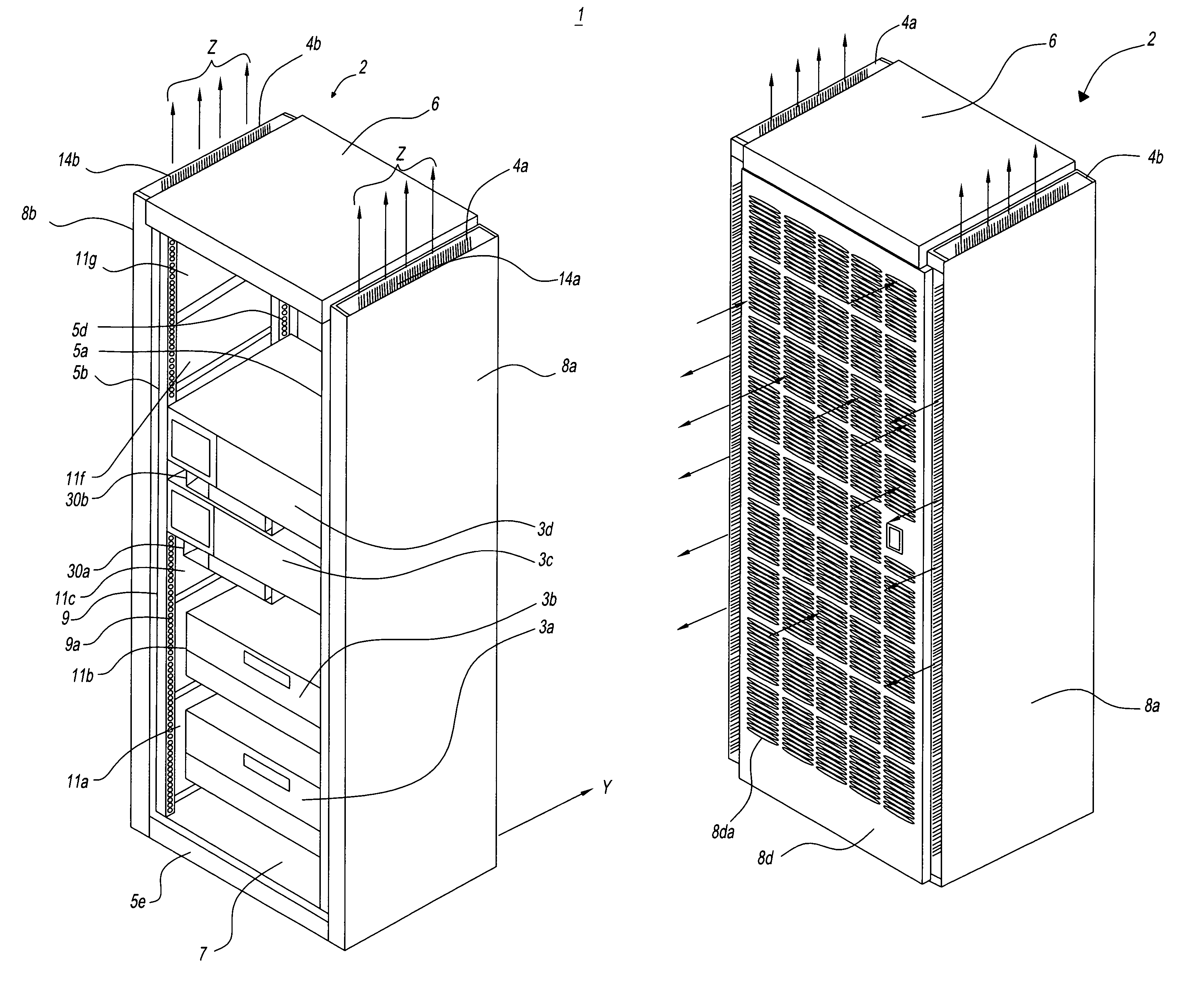
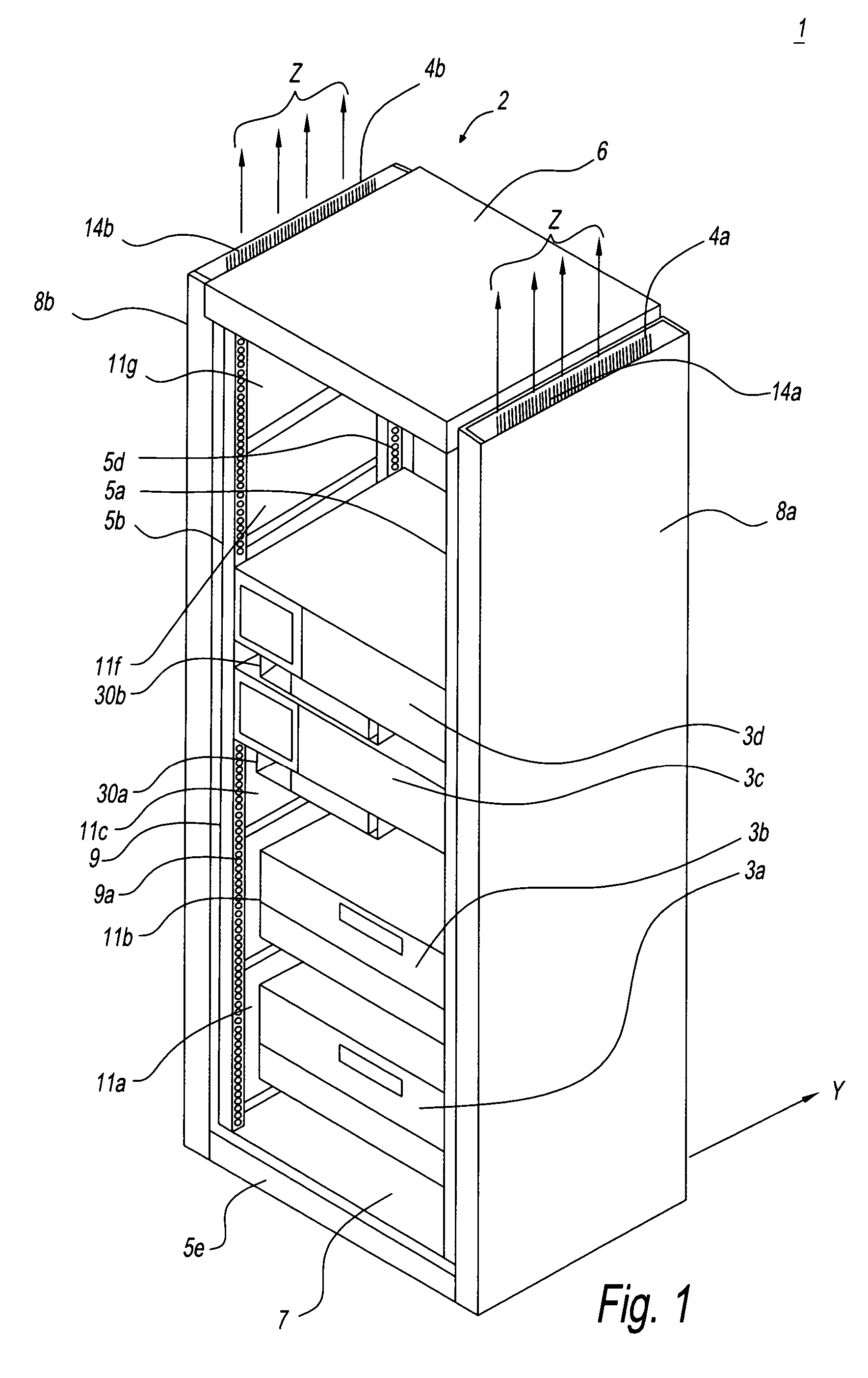
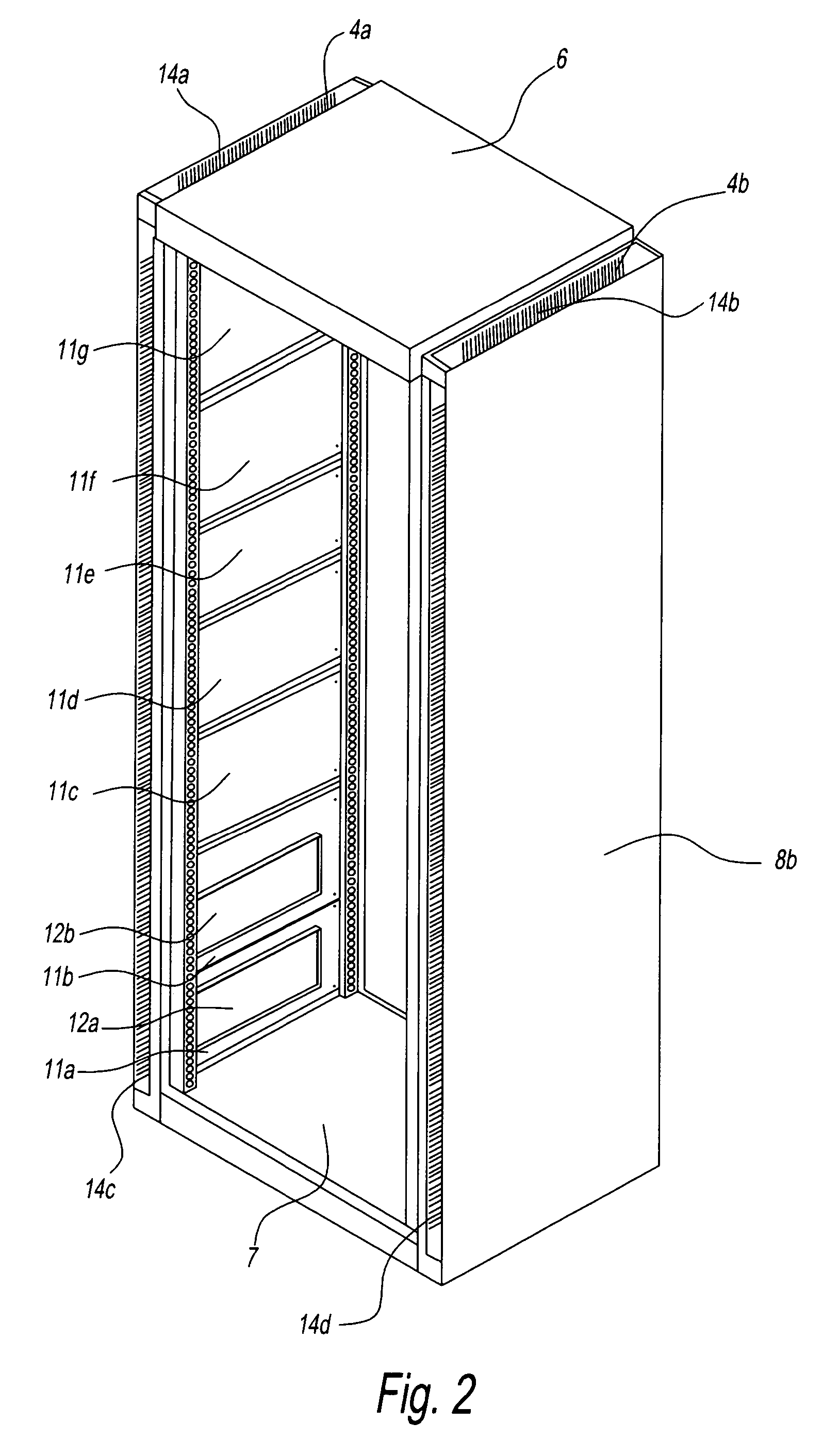
[0040]Embodiments of the present invention are described below while referring to the drawings. FIG. 1 is an oblique view showing the instrument rack of one embodiment of the present invention and shows the state where the electronic devices are mounted and the front door is removed to see inside. FIG. 2 is an oblique view showing the same instrument rack of one embodiment of the present invention in the same state as in FIG. 1, but it is a drawing seen from the back with the mounted electronic devices removed. The entire unit, including the electronic devices represented by symbol 1, in FIGS. 1 and 2 comprises the instrument rack (referred to below as the “rack”) having air ducts 4 and electronic devices 3.

[0041]Rack 2 in FIGS. 1 and 2 has support columns 5 (5a, 5b, 5c (not illustrated), 5d), top plate 6, base plate 7, and side covers 8 (8a, 8b), and preferably the entire unit is formed to meet standard dimensions. It should be noted that the side covers form the sides of air ducts...


PUM


Abstract

A rack for holding on its inside multiple electronic devices, which have fans for drawing outside air to inside the devices and exhaust ports for discharging air, including two pairs of support columns, the columns of each pair being placed parallel to one another in the front and the back at a pre-determined distance apart from one another, and air ducts for directing exhaust air from the above-mentioned exhaust ports of these electronic devices positioned between at least one pair of the two pairs of support columns, having a structure wherein there are side covers that cover the side surfaces, and the air ducts are installed between the pair of support columns between the side covers and the inside of the rack and are substantially formed from multiple panels adjacent to one another inside of the rack.

Description

BACKGROUND OF THE INVENTION[0001]1. Field of the Invention[0002]The present invention relates to a rack for electronic devices and equipments that generate heat and in particular to a low-cost instrument rack with high warm-air discharge efficiency.[0003]2. Description of the Related Art[0004]Many diverse electronic devices: personal computers, measuring instruments and others have been installed in places ranging from business offices to factories in recent years, and the environmental conditions under which each electronic device is used have become critical as a result. For instance, there are cases in which multiple electronic devices are mounted in vertical arrangements inside a rack for mounting equipment for the purpose of efficient use of room space.[0005]Electronic devices for this type of rack mount are generally equipped with fans that cool each electronic device because when the temperature of each electronic component in the device housing increases too much due to the ...

Claims


Application Information

Patent Timeline
Patent Type & Authority Patents(United States)
IPC IPC(8): F25D17/08H05K7/18H05K7/20
CPCH05K7/20572
Inventor TACHIBANA, JUNICHI
Owner ADVANTEST CORP
Why Eureka
Try Eureka