Pixelated photon detector

a photon detector and detector technology, applied in the direction of instruments, radiation measurement, electrical equipment, etc., can solve the problems of scintillation light in both nai(tl) and bgo crystals, low stopping power per gram of material, and relatively low density of nai(tl)

Inactive Publication Date: 2006-03-07
ELGEMS
View PDF25 Cites 48 Cited by
  • Summary
  • Abstract
  • Description
  • Claims
  • Application Information

AI Technical Summary

Benefits of technology

[0018]One aspect of some preferred embodiments of the present invention is related to improved methods f

Problems solved by technology

However, NaI(Tl) has a relatively low density and low stopping power per gram of material.
BGO scintillation crystals on the other hand exhibit low light output for detected photons and therefore generally poor energy resolution Furthermore, scintillation light in both NaI(Tl) and BGO crystals caused by the passage of a photon through the crystal lasts for a relatively long time.
This complicates accurate coincidence timing using these detectors.
However, it difficult to manufacture thick semiconductor crystals for photon detectors using present state of the art technology.
However, signals from anode pixels of a pixelated detector of this type are highly variable in

Method used


Image

  • Pixelated photon detector
  • Pixelated photon detector
  • Pixelated photon detector

Examples


Embodiment Construction

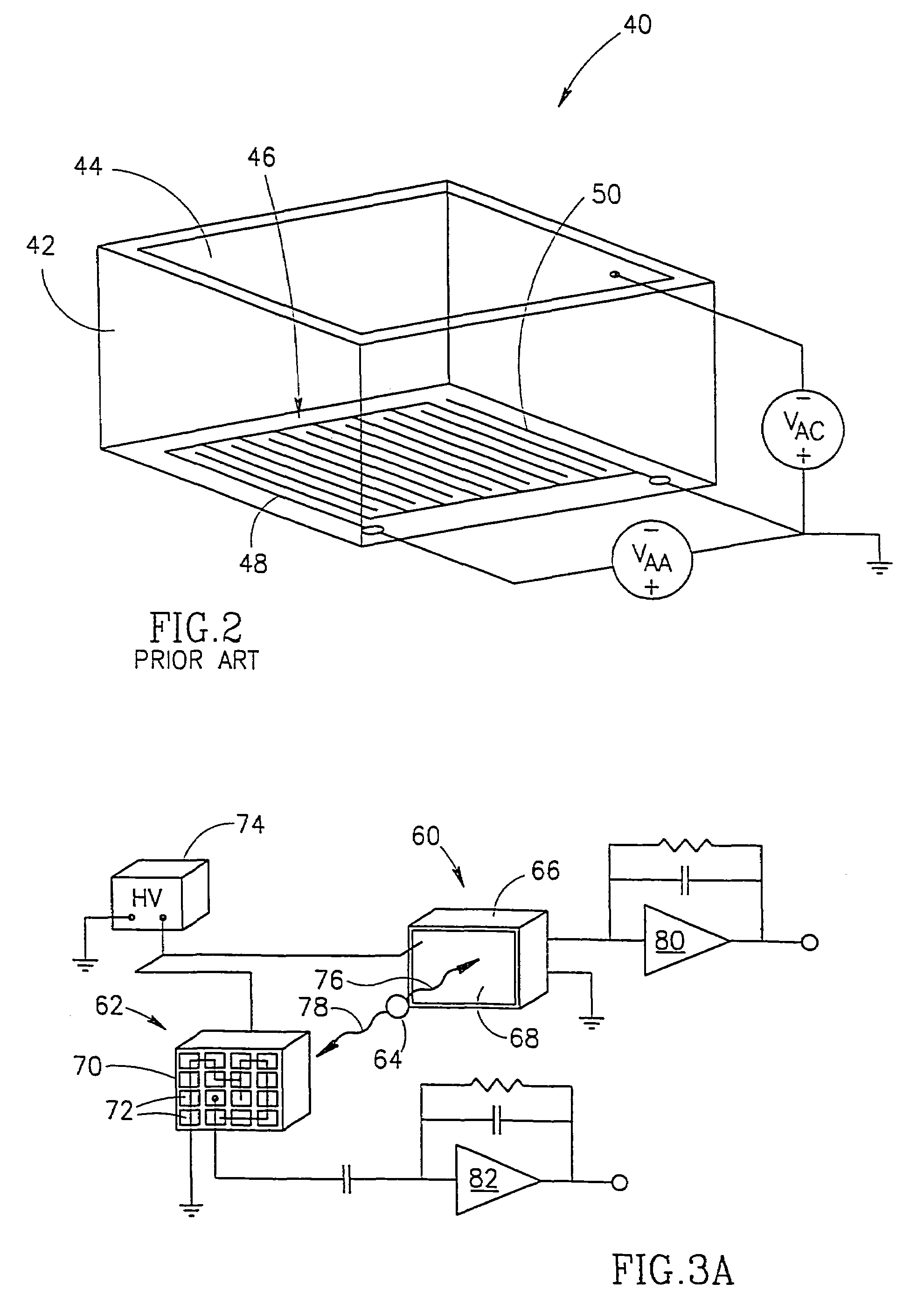
[0106]FIGS. 3A, 4A and 5A schematically show a series of experiments performed by the inventors of the present invention that demonstrate the time resolution of different signals from a pixelated detector.

[0107]The experiment illustrated in FIG. 3A demonstrates the relatively poor time resolution of timing signals from single anode pixels, which signals are affected by the small pixel effect. The experiment illustrated in FIG. 4A demonstrates the greatly improved time resolution of timing signals from the cathode of a pixelated detector, in accordance with a preferred embodiment of the present invention. The experiment illustrated in FIG. 5A demonstrates that a timing signal from a pixelated detector that is a sum of signals from anode pixels of the detector can provide even better time resolution than a timing signal from the cathode of the detector, in accordance with a preferred embodiment of the present invention.

[0108]Each of the experiments consisted of exposing two identical ...


PUM


Abstract

A gamma camera comprising:
a plurality of pixelated detectors wherein each pixelated detector provides a detector signal responsive to photons that are incident on it;
a plurality of processing circuits that receive said detector signals and provide processed signals responsive to said detector signals; and
at least one printed circuit board on which said processing circuits are mounted and having conductors thereon that carry said detector signals to said processing circuits;
wherein said processing circuits are mounted on said printed circuit board at locations remote from said detectors; and
wherein said plurality of pixelated detectors form a two-dimensional planar array.

Description

RELATED APPLICATIONS[0001]The present application is a divisional application of U.S. application Ser. No. 10 / 465,075, filed on Jun. 19, 2003 now U.S. Pat. No. 6,740,885 which is a divisional application of U.S. application Ser. No. 09 / 806,084, filed on Jun. 22, 2001, now U.S. Pat. No. 6,621,084 which is a U.S. national application of PCT Application No. PCT / IL98 / 00462, filed on Sep. 24, 1998. The disclosures of all of these applications are incorporated herein by reference.FIELD OF THE INVENTION[0002]The invention relates to solid state photon detectors and in particular to the timing and energy resolution of pixelated photon detectors.BACKGROUND OF THE INVENTION[0003]Single photon emission computerized tomography (SPECT) and positron emission tomography (PET) depend upon the detection of gamma ray photons emitted by, or generated as a result of, radio-pharmacological compounds introduced into the body to image regions of the body. Photon detectors used in SPECT and PET imaging sys...

Claims


Application Information

Patent Timeline
IPC IPC(8): G01T1/172G01T1/24G01T1/29
CPCG01T1/172G01T1/2928G01T1/244G01T1/241G01T1/242G01T1/2985
Inventor WAINER, NAORHEFETZ, YARONAMRAMI, AHARONPANSKY, AMIR
Owner ELGEMS
Why Eureka
Try Eureka