Method in depositing metal oxide materials

a metal oxide and depositing technology, applied in chemical vapor deposition coatings, coatings, special surfaces, etc., can solve the problems of reducing production capacity, non-uniformities can be problematic, and the ald-type technology is self-limiting, so as to improve uniformity in downstream zones, improve uniformity, and improve uniformity

Active Publication Date: 2010-07-01
BENEQ OY
View PDF7 Cites 49 Cited by
  • Summary
  • Abstract
  • Description
  • Claims
  • Application Information

AI Technical Summary

Benefits of technology

[0114]When chloride and water precursors are supplied through a common delivery line, upstream to the object to be coated, they generate HCl by-product which will function in a manner similar to that of the modificators of the present invention, and improve uniformity in the downstream zones. If the amount of HCl is large enough in relation to the object being coated, the effect of the modificator may be smaller. It is possible to improve uniformity by adding surface in front of the objects to be coated. The purpose of this added surface, for example with chlorides, is to generate HCl by-product gas, which eventually improves uniformity in the downstream region. This added surface may reduce production capacity and increase cost. In other words, the present invention is of high importance in batch applications, in the coating of large areas and long objects.
[0115]One surprising effect of the modificator was that both effects of the object to be coated itself and effects from the surrounding surfaces on the deposited film were greatly reduced. It is possible that molecular water exists on the surface without the modificator, and the environment affects the water molecules. This effect is especially strong with TiO2 film. These effects have caused difficulties to develop high capacity ALD batch processes. The use of modificator makes it possible to bring coated surfaces very near each other, and it also reduces the effects on the film being deposited originating from the substrate itself. The distance between substrate surfaces may be less than 12 mm, preferably less than 5 mm, more preferably less than 1 mm. The distance between surfaces to be coated may be even less than 1 micrometer.
[0116]Although the proposed method was tested at vacuum pressures, it is possible that this method also provides positive effects in atmospheric and high-pressure ALD processing systems.

Problems solved by technology

ALD-type technologies are self-limiting processes.
However, this does not mean that the resulting deposited material is uniform over the whole coated object.
These non-uniformities can be problematic, for instance:Uneven materials thickness or another material property reduces the production capacity or can prevent coating of large objects.The thickened portions of the layer can adversely affect step coverage.
This mode has limitations in batch applications when objects to be coated are stacked.
The use of plasma is difficult with batch tools where the objects to be coated are stacked, because the plasma may not distribute well and evenly inside the batch.
For example, semiconductor memories and large-area substrates may have deep trenches, and to expose and purge these trenches a long time is required.
In practice, the batch ALD process often leads to more non-uniformity than does the same precursor chemistry when single wafer deposition tools are used.
Unfortunately, many ALD processes using chlorides are well known for the decreasing thickness in the precursor flow direction.
Many ALD processes using water suffer from the variation of the growth rate due to variation of the amount of dosed water, and sometimes due to the purge time after the water dose.
This growth rate dependency on the water dose causes problems, especially with large coated areas and in batch setups.
For example, differences in the water vapor flow causes varying local partial pressures, resulting in varying exposure of the surface to precursors.
However, a lot of unsolved problems remain in the details of the water molecule structure and its relation to the forces acting between molecules.
1. “One (little studied) source is a downstream non-uniformity issue caused by upstream reaction by-products.
2. “Although there are no comprehensive results to show how the uniformity degrades on the substrate, there is a strong assumption that non-uniformity is mainly caused by the hydrogen chloride by-product.” The article describes three proposed theories for explaining the non-uniformity; however, no methods to reduce the non-uniformity of halide processes are suggested.
“As with the metal halide processes, the metal alkoxide processes suffer from a small thickness non-uniformity, i.e., decreasing film thickness in the flow direction.
However, up-scaled processes for large areas and batches have a clear uniformity profile and may require a sacrificial zone in front of the deposition area.
This reduces capacity and increases cost.
However, the article does not teach how to decrease this non-uniformity.
Test runs carried out over the years by the present inventors have confirmed that the effects described by Ritala exist, and that they cause difficulties when surfaces are near each other.
However, this prior art application does not provide any information on the possible benefits or effects when said combinations are carried out.
In batch setups, several phenomena occur which are not easily visible from the results of single wafer tool processes.Small distances between surfaces may cause strange effects.
This effect causes difficulties to increase deposition capacity.
Thus all effects from by-products are the stronger, the smaller is the distance (and the higher the deposition capacity) between surfaces.An enlarged deposition area increases by-product partial vapor pressures and causes effects from by-products, similar to those of a decreased flow channel area.Non-uniformity eventually causes flaking of the cumulative film on the coated jigs, walls and other construction parts.
This causes increased cost due to required cleaning.
Similarly, ethanol is proposed as a cause of the non-uniformity in the metal alkoxide processes.
However, HCl is a dangerous, corrosive gas and thus often not accepted in the production environment.

Method used


Image

  • Method in depositing metal oxide materials
  • Method in depositing metal oxide materials
  • Method in depositing metal oxide materials

Examples


example 1

TiO2 Deposition

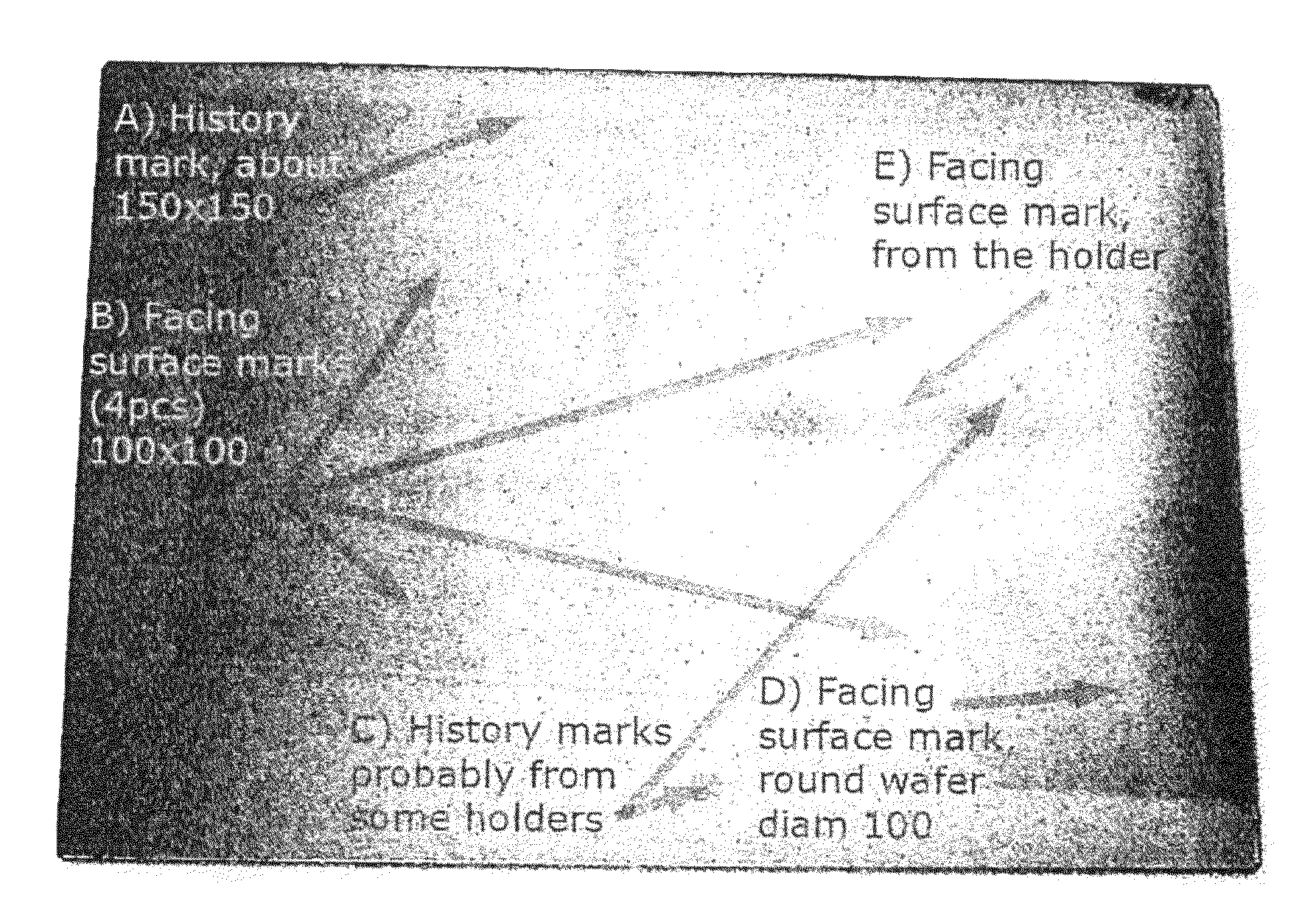
[0168]The ALD deposition zone included a batch cassette with 36 shelves. The distance between shelves was about 4.5 mm (surface to surface). The width of the shelf was 240 min and length 500 mm. Pieces of silicon wafer were loaded onto shelf number 19, in the middle of the cassette, and measurements were made from these pieces.

[0169]The heated reaction zone was allowed to stabilize for about 6 hours, during which time the reaction zone reached a temperature of about 280° C.

[0170]The used pulse lengths, total cycle count and resulting average thickness are given in table 1. Thickness and refractive index results are given in charts 1 and 2.

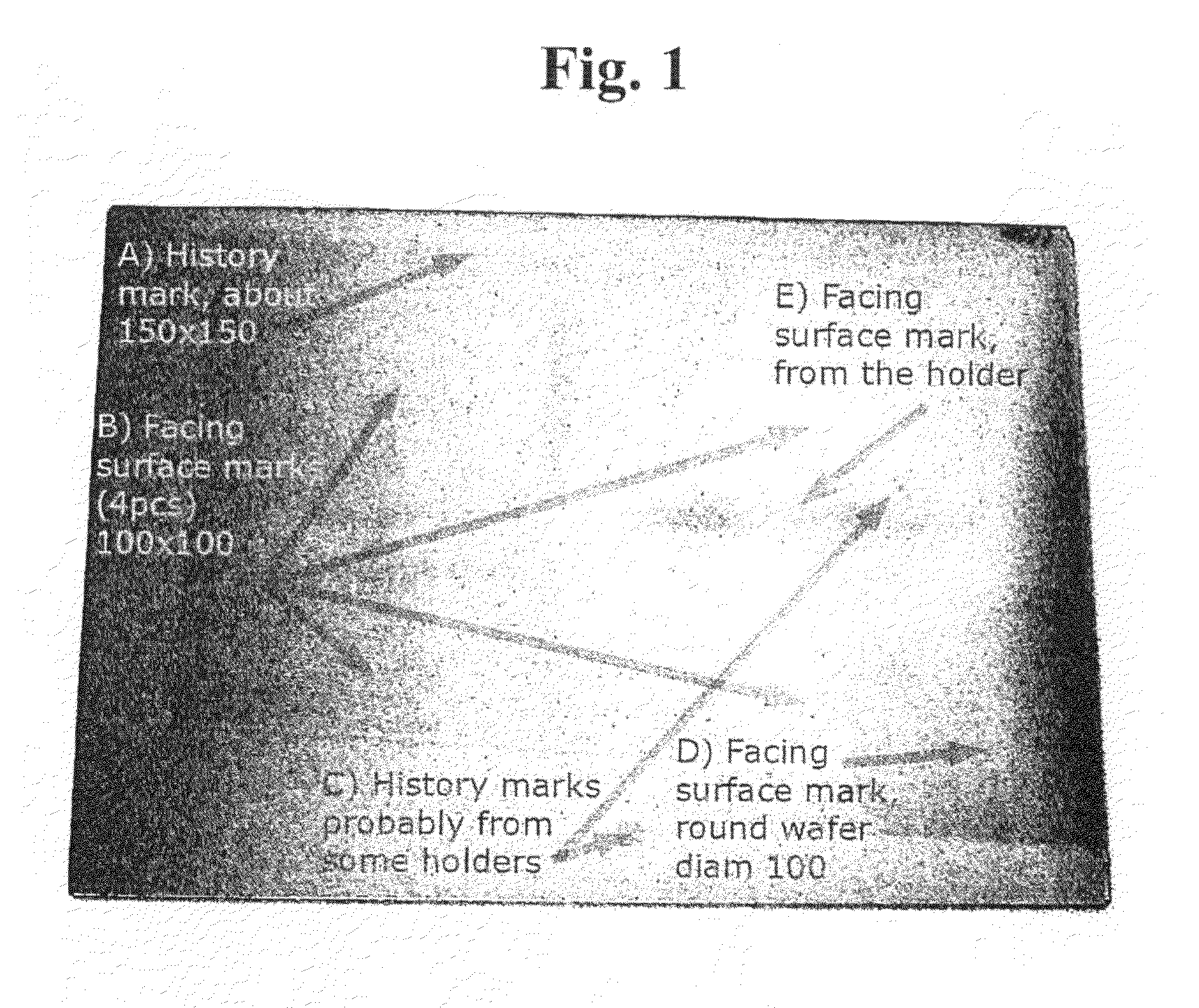
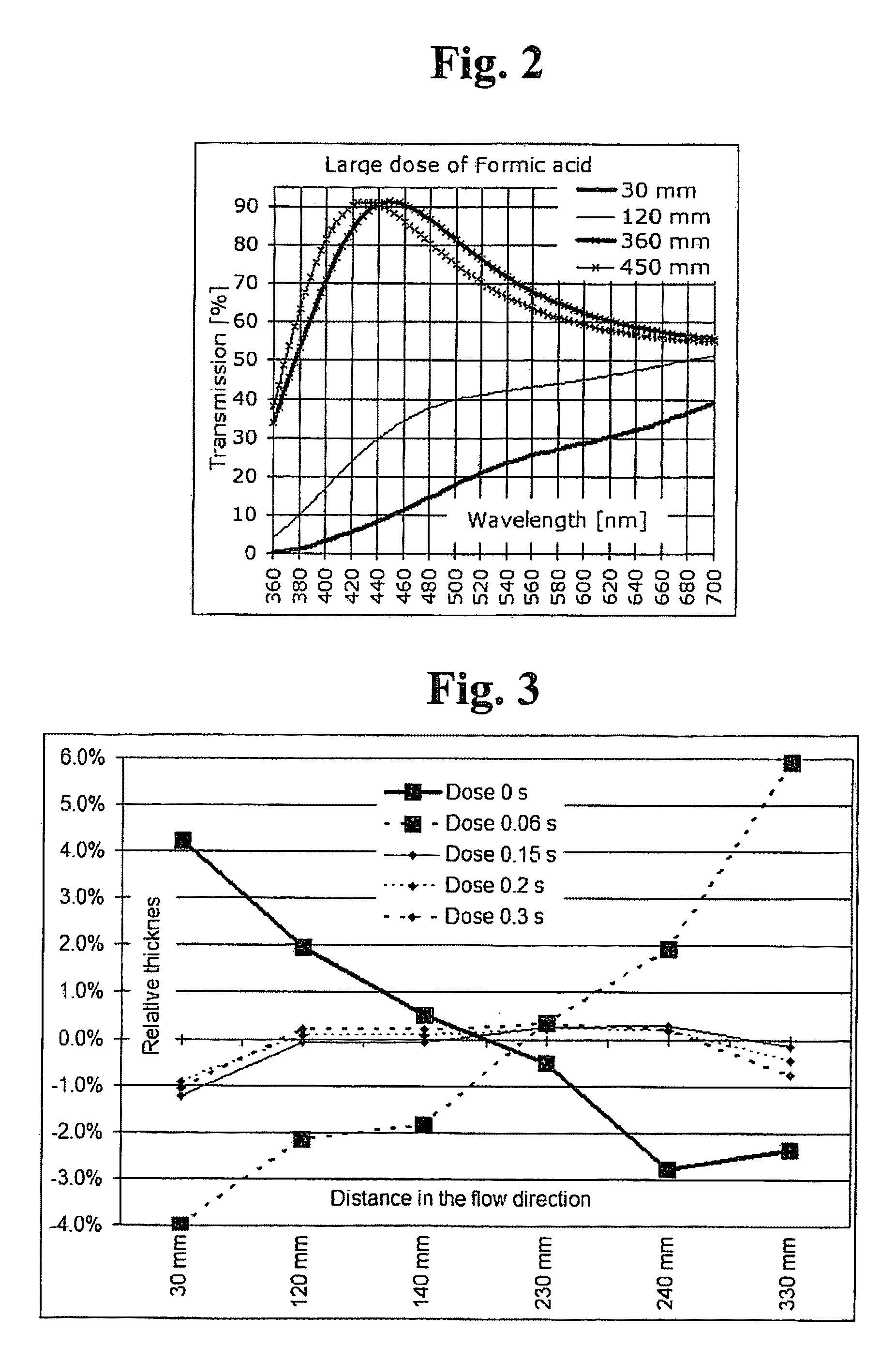
[0171]The change of the thickness profile is clearly visible in the chart 1. The use of ethanol decreased the growth rate on the inlet side. Ethanol also increases the refractive index, indicating that the deposited material is more dense than without modificator. Abnormally large water doses were used without ethanol to demonstrate ...

example 2

Al2O3 Deposition

[0173]The ALD deposition zone included a batch cassette with 36 shelves. The distance between shelves was about 4.5 mm (surface to surface). The width of the shelf was 240 mm and length 500 mm. Pieces of silicon wafer were loaded onto shelf number 19, in the middle of the cassette, and measurements were done from these pieces.

[0174]The heated reaction zone was allowed to stabilize for about 6 hours, during which time the reaction zone reached a temperature of about 280° C.

[0175]The used pulse lengths, total cycle count and resulting average thickness are shown in Table 2. Thickness and refractive index results are shown in charts 3 and 4.

[0176]The change of the thickness profile is clearly visible in chart 3. The use of the ethanol decreased the growth rate at the inlet side. Ethanol also increased the refractive index, indicating that the deposited material is more dense.

TABLE 5Without ethanolWith ethanolTotal cycle count12001200AlCl3 dose1.40s1.40sPurge2.10s2.10sH2...

example 3

HfO2 Deposition

[0177]The ALD deposition zone included a batch cassette with 23 shelves. The distance between shelves was about 8 mm (surface to surface). The width of the shelf was 240 mm and length 360 mm. Pieces of silicon wafer were loaded onto shelf number 13, in the middle of the cassette, and measurements were made from these pieces.

[0178]The heated reaction space was allowed to stabilize for about 3 hours, during which time the reaction space and object to be coated reached a temperature of about 300° C.

[0179]The used pulse lengths, total cycle count and resulting average thickness are shown in table 6. Thickness and refractive index results are shown in charts 5 . . . 8.

[0180]The change of the thickness profile is clearly visible in charts 5 and 7. The use of ethanol decreased the growth rate on the inlet side. Two sets of runs were done:

[0181]Runs 579 and 580 had smaller HfCl4 dosing. The purge between H2O and ethanol was short. Ethanol dosing was smaller. The purge between...


PUM

PropertyMeasurementUnit
distanceaaaaaaaaaa
distanceaaaaaaaaaa
thicknessaaaaaaaaaa

Abstract

The present invention relates to a method for enhancing uniformity of metal oxide coatings formed by Atomic Layer Deposition (ALD) or ALD-type processes. Layers are formed using alternating pulses of metal halide and oxygen-containing precursors, preferably water, and purging when necessary. An introduction of modificator pulses following the pulses of the oxygen-containing precursor affects positively on layer uniformity, which commonly exhibits gradients, particularly in applications with closely arranged substrates. In particular, improvement in layer thickness uniformity is obtained. According to the invention, alcohols having one to three carbon atoms can be used as the modificator.

Description

FIELD OF THE INVENTION[0001]The present invention relates to methods of manufacturing materials by employing sequential surface reactions. More particularly, the present invention relates to methods of manufacturing materials by employing an Atomic Layer Deposition (ALD)-type process. The presented method improves uniformity and / or enables to modify properties of materials prepared from metal halide precursors and precursors containing oxygen, said materials being deposited by using ALD processes and ALD-type processes.DEFINITIONS AND CONCEPTS[0002]Atomic Layer Deposition (ALD) has been used for over 30 years. Workers with various backgrounds have described, within this technique, the use of a great variety of combinations of chemicals, and an extremely wide range of methods and applications to combine chemicals.[0003]For the purpose of this text, the following definitions are used. In other literature pertaining to ALD technology, the terminology may be different.[0004]A material c...

Claims


Application Information

Patent Timeline
Patent Type & Authority Applications(United States)
IPC IPC(8): H01L21/473C23C16/08C23C16/40C23C16/455
CPCC23C16/403C23C16/405C23C16/45534
Inventor MAULA, JARMOHARKONEN, KARI
Owner BENEQ OY
Why Eureka
Try Eureka