Parallel linkage and artificial joint device using the same

a technology of parallel linkage and artificial joint, which is applied in the direction of rod connection, prosthesis, ligament, etc., can solve the problems of increasing the manufacturing cost of the device, the size of the power supply and the whole device, and the difficulty of turning motion, so as to reduce the burden of the user wearing the artificial leg, reduce the kicking force, and soften the shock transmitted

Inactive Publication Date: 2006-10-10
HONDA MOTOR CO LTD
View PDF2 Cites 133 Cited by
  • Summary
  • Abstract
  • Description
  • Claims
  • Application Information

AI Technical Summary

Benefits of technology

[0031]More preferably, the artificial joint device further comprises urging members provided in the plurality of expansible links, respectively, each for urging a corresponding one of the expansible links in at least one opposite direction to directions in which the expansible link expands and contracts, when the expansible link expands and contracts.
[0032]According to this preferred embodiment, the same advantageous effects as provided by the above parallel linkage can be obtained. More specifically, it is possible to absorb shock transmitted between the two limb members via the expansible links. Therefore, when the artificial joint device is applied e.g. to an ankle joint of an artificial leg, the urging members serve to soften shock transmitted from the artificial leg to a user's living body via the expansible links when the user puts the artificial leg on a floor, a road surface, or the like (hereinafter simply referred to as “the floor”), to thereby reduce burden on the user wearing the artificial leg. In addition, if the urging members urge the respective expansible links when they contract, in a direction opposite to the contracting direction, when the user is lifting the artificial leg up from the floor while walking, urging forces urging the artificial leg to kick against the floor can be obtained, and hence it is possible to reduce a kicking force from the walking living body, thereby further reducing burden on the user wearing the artificial leg, and enabling the user to perform smoother walking motion. Further,

Problems solved by technology

According to the above conventional artificial joint device, since the foot portion and the leg portion are allowed to perform pivotal motion with respect to each other about the horizontal axis, only in the front-rear direction, even when a person wearing the artificial leg tries to turn left or right while walking, the ankle joint po

Method used


Image

  • Parallel linkage and artificial joint device using the same
  • Parallel linkage and artificial joint device using the same
  • Parallel linkage and artificial joint device using the same

Examples


first embodiment

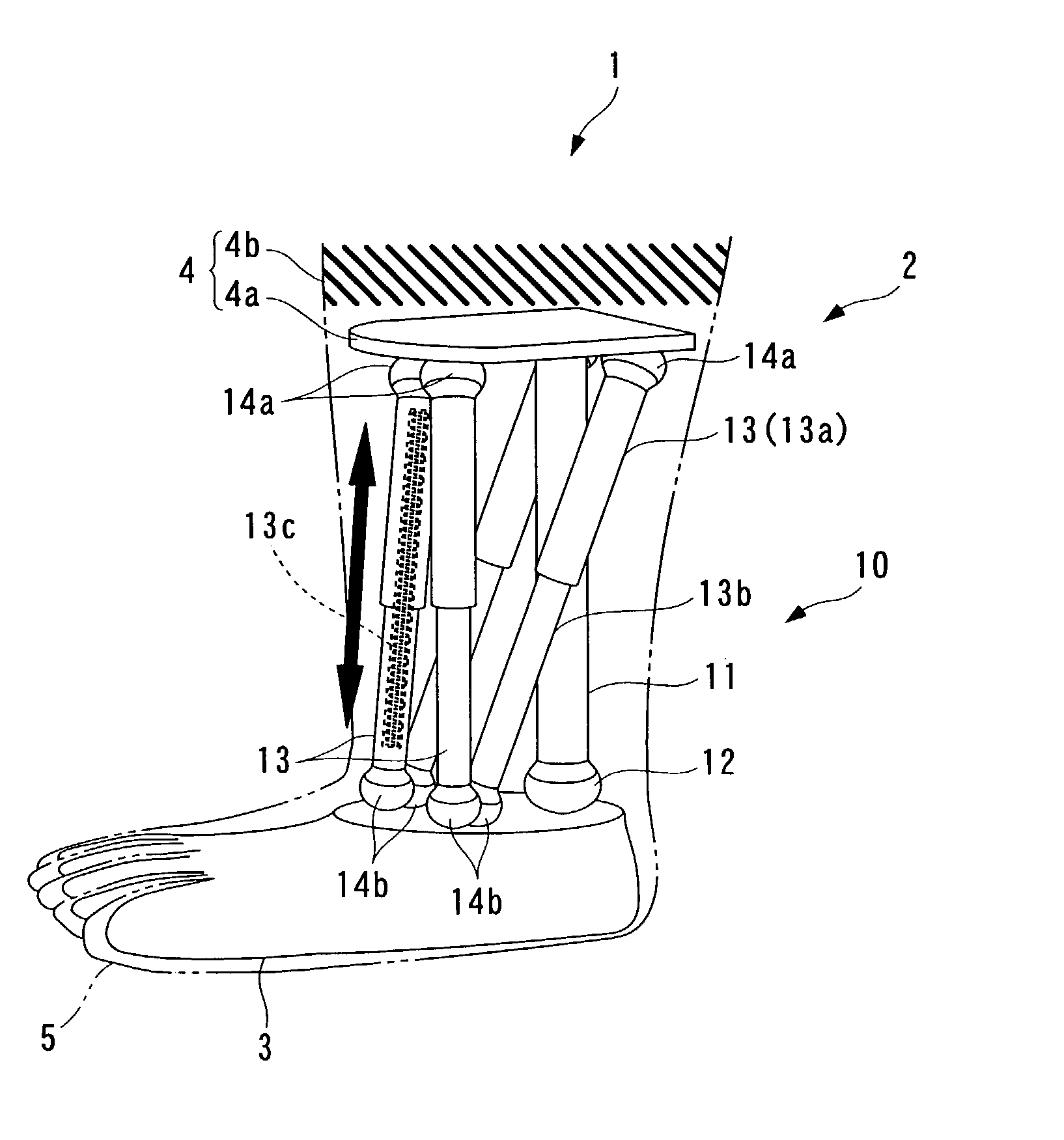
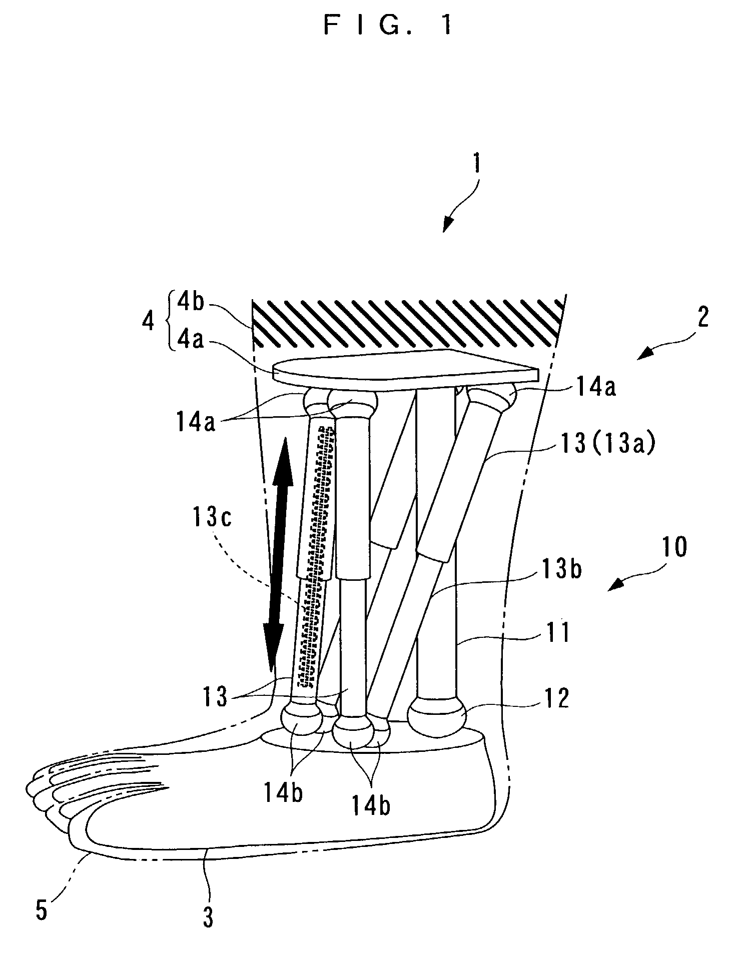
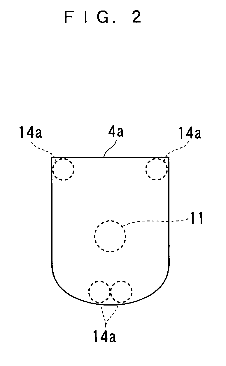
[0076]Referring first to FIG. 1, there is schematically shown the construction of an artificial leg 1 in which an artificial joint device 2 including a parallel linkage according to the invention is applied to an ankle joint thereof. In the following description, the left and right sides and the front and rear sides as viewed from a user wearing the artificial leg are referred to as the left and right sides and the front and rear sides, respectively (more specifically, the left and right sides as viewed in FIG. 1 are referred to as the front and rear sides, respectively, and the front and rear sides as viewed in the same are referred to as the left and right sides, respectively).

[0077]As shown in the figure, the artificial leg 1 is a type attached to an under-knee leg portion of a living body, and used for a right leg. The artificial leg 1 includes a foot portion 3 and a leg mounting portion 4, the artificial joint device 2 connecting these portions by a parallel linkage 10, and a c...

second embodiment

[0100]Although in the above second embodiment, the coil spring 11c is used as the shock-absorbing member for reducing the shock transmitted to the living body via the fixed link 11, this is not limitative, but the shock-absorbing member may be implemented by any suitable means having a shock-absorbing property. For instance, a fluid spring, such as an air spring, or a synthetic rubber may be employed.

[0101]Next, an artificial joint device according to a third embodiment of the present invention will be described with reference to FIGS. 9A to 11B. The artificial joint device of the present embodiment is applied to an artificial joint device for an ankle joint of an electrically controlled artificial leg and an artificial joint device for a joint at the ball of the foot. First, a description is given of the artificial joint device 2 for the ankle joint. This artificial joint device 2 is distinguished from the artificial joint device 2 of the first embodiment in that it includes electr...

third embodiment

[0113]Although in the above third embodiment, the implant chip 24 is used as detection means for detecting the signal indicative of the user's operating will, this is not limitative, but any suitable means capable of detecting a user's operating will may be employed as the detection means. For instance, it is possible to use a sensor for detecting changes in a potential of the nervous system, a sensor for detecting the movement of muscles, a sensor for detecting a user's voice, etc.

[0114]Further, although in the third embodiment, the movable link 19 is used as means for preventing the length of the hallux from being changed during bending motion of the joint at the ball of the foot, the movable link 19 may be omitted, and expansion and contraction of the expansible links 17 may be controlled by the controller 21 to hold the length of the hallux almost constant during bending motion of the joint at the ball of the foot. This makes it possible to further approximate the bending motion...


PUM


Abstract

There are provided an artificial joint device that can realize an artificial limb enabling twisting motion without a drive source, and when with the drive source, reduce the size and costs of the device, and a parallel linkage that can realize the device. The linkage connects a foot portion and a mounting plate spaced from each other. A fixed link has one end fixed to the plate, and the other end connected to the foot portion via a ball joint, making the angle of the fixed link relative to the foot portion changeable in any direction. Expansible links extend between the foot portion and the plate in an expansible/contractible manner and each have opposite ends connected to the plate and the foot portion via respective upper and lower ball joints, making respective angles thereof relative to the foot portion and the plate changeable in any direction.

Description

BACKGROUND OF THE INVENTION[0001]1. Field of the Invention[0002]This invention relates to an artificial joint device and a parallel linkage, which are applied to an artificial limb, such as a prosthetic limb or a limb of a robot.[0003]2. Description of the Prior Art[0004]Conventionally, an artificial joint device of the above-mentioned kind has been disclosed e.g. in Japanese Laid-Open Patent Publication (Kokai) No. 11-345. The artificial joint device is applied to an ankle joint for connecting between a foot portion of an artificial leg and a leg portion of the same. The foot portion of the artificial leg has an upper end portion thereof formed with a through hole extending laterally. On the other hand, the leg portion of the artificial leg has a lower end thereof bifurcated into two arms to form a bracket with each arm having a hole formed therethrough at a location corresponding to an opening of the through hole extending laterally through the foot portion. In this artificial joi...

Claims


Application Information

Patent Timeline
IPC IPC(8): A61F2/48A61F2/70A61F2/00A61F2/50A61F2/54A61F2/58A61F2/60A61F2/64A61F2/66A61F2/72A61F2/74B25J17/02B25J19/00B62D57/02
CPCA61F2/60A61F2/66A61F2/6607B25J17/0266B25J19/0091B62D57/02B25J9/0057A61F2/583Y10T403/7077A61F2/72A61F2002/30517A61F2002/5001A61F2002/5003A61F2002/5059A61F2002/5066A61F2002/5072A61F2002/5075A61F2002/5084A61F2002/5098A61F2002/543A61F2002/587A61F2002/6621A61F2002/701A61F2002/704A61F2002/747A61F2002/7625A61F2220/0025A61F2002/708Y10T403/32008Y10T403/32032A61F2/586A61F2/74
Inventor YASUI, YUJIKIYOMOTO, HIROSHIUSUKURA, ISAONAKAHARA, YOUICHIIWASAKI, HARUYUKIUMEDA, SHUNGOYAMAMOTO, KAZUNORISHIONO, MASAMITSUOKADA, KAZUONAKAYAMA, MANABUKUBO, ATSUSHI
Owner HONDA MOTOR CO LTD
Why Eureka
Try Eureka