
Very bright scintillators

Active Publication Date: 2009-11-03
RADIATION MONITORING DEVICES
View PDF13 Cites 36 Cited by
  • Summary
  • Abstract
  • Description
  • Claims
  • Application Information

AI Technical Summary

Benefits of technology

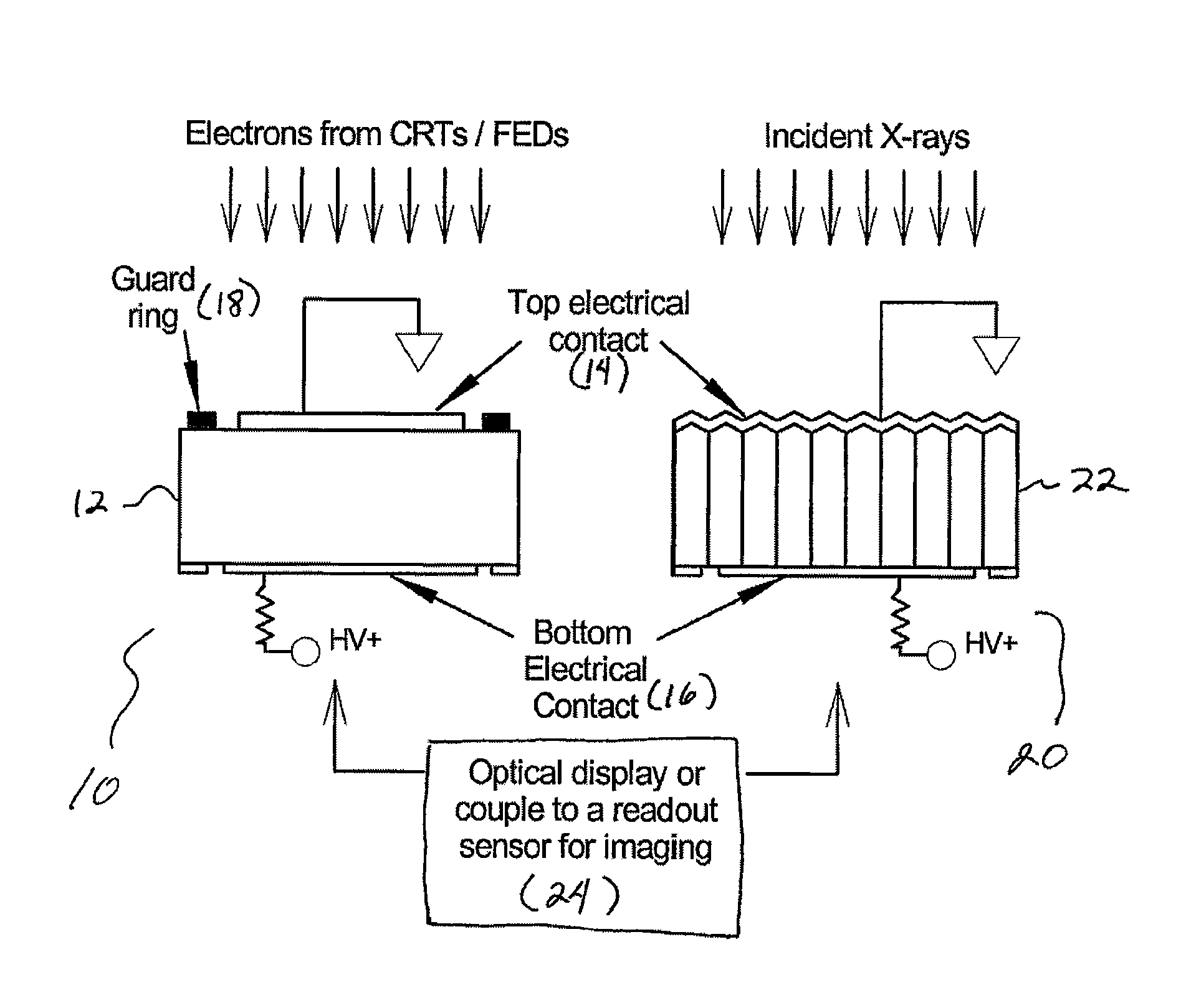
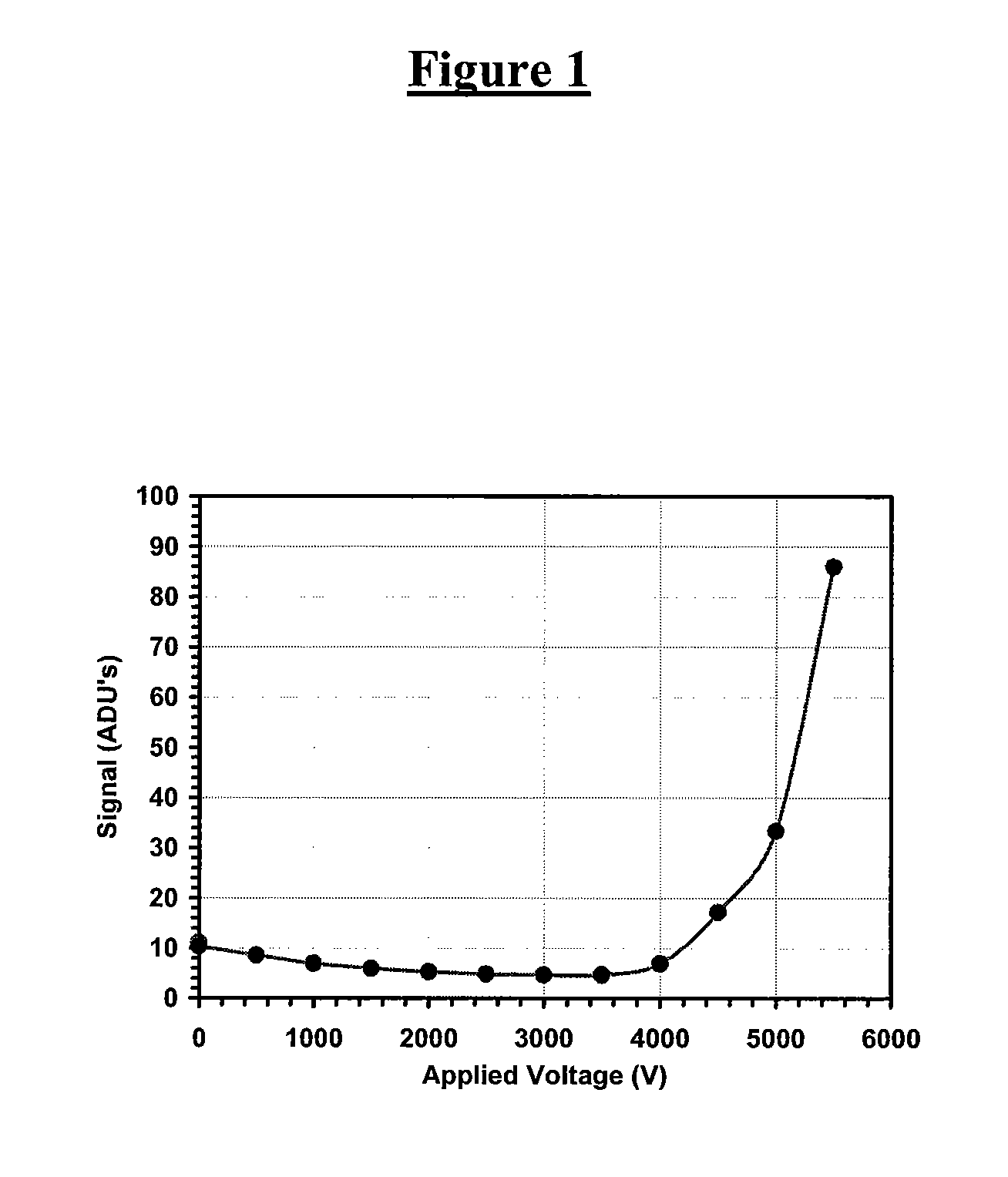
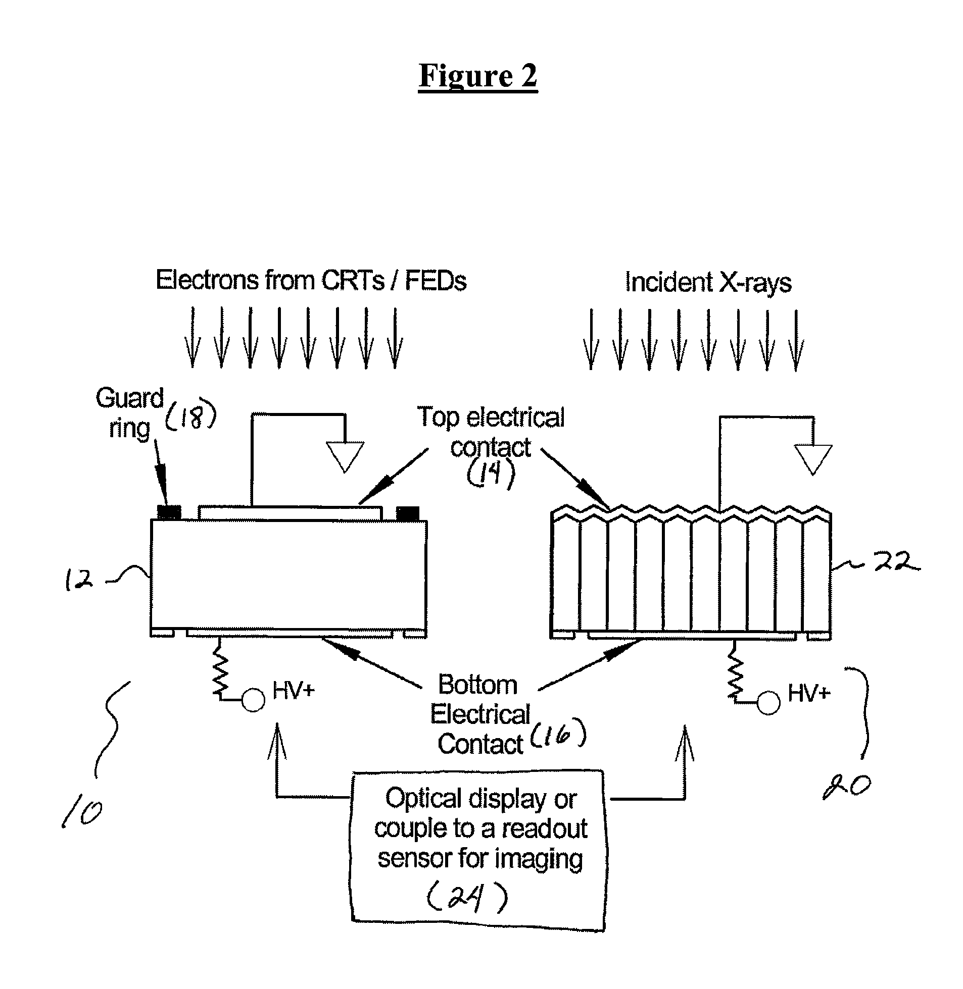
[0010]The present application discloses methods and devices where under the application of a very high intensity electric field, a scintillator exposed to ionizing radiation can provide light outputs that far exceeds those previously obtained in the art. In a particular embodiment of the invention a light output gain on a scale of magnitudes has been achieved from a thick single crystal scintillator film as compared to that previously achieved with a “state-of-the-art” cathodoluminescent phosphor powder or a scintillation crystal. The light output gains are on the order of 10 to 100 times those obtained with prior methods, and will make it possible to achieve sufficient brightness from, for example, an FED for it to serve as a digital video projector. In the field of x-ray imaging, such a bright scintillator will have tremendous potential in many important applications, such as computed tomography (CT), SPECT, and diagnostic digital radiology.
[0011]In one embodiment of the present invention a CsI(Tl) scintillator structure is provided that can achieve a large gain in luminescence, light yield, from a thick scintillator film or scintillator crystal, when under the influence of an intense internal electric field. The film can be in the form of a thick crystalline slab of a scintillator such as for example, CsI(Tl), or in the form of a microcolumnar structure to achieve the required gains. A device comprising the scintillator and an assembly for attaching a plurality of opposed electrodes is combined with an ionizing radiation source and alternatively an optically coupled light detector.
[0012]Thus, in one aspect the present invention provides a method to obtain luminescence gain from a scintillator. Such a method includes providing a scintillator and applying an electric field to the scintillator so as to increase luminescence output of the scintillator during radiation detection.
[0013]In another aspect, the present invention provides a device to obtain luminescence gain from a scintillator by application of an electric field to the scintillator. The device includes a scintillator and an assembly for coupling a plurality of electrodes to the scintillator so as to provide an electric field to the scintillator to increase luminescence output of the scintillator during radiation detection.
[0016]Devices and assemblies of the present invention can be combined with or incorporated into a variety of devices making use of scintillation based radiation detection. For example, in another aspect of the present invention, a cathode ray tube (CRT) device is provided. The device includes a cathode ray tube, a scintillator coupled to a face of a CRT substrate, and an assembly for coupling a plurality of electrodes to the scintillator so as to provide an electric field to the scintillator to increase luminescence output of the scintillator during radiation detection. The device further includes an energy source coupled to the plurality of electrodes to provide the electric field to the scintillator, and an activated electron source.

Problems solved by technology

In spite of these advantages, CRTs are losing in the marketplace as television displays and projectors based on liquid crystal concepts, e.g., liquid crystal displays (LCDs), micro-mirror digital light processors, and plasmas have evolved in recent years.
Similarly, field emission displays (FEDs), a breakthrough in imaging technology, have fallen out of favor in comparison to liquid crystal displays (LCDs) and plasma display technologies.
The limitation of CRT and FED technologies arises from the current cathodoluminescent phosphors used in these devices.
These phosphors limit the display brightness due to their low output, reduced contrast due to their amorphous structure, and need for high voltage across the tube for their operation.
However, as advanced as the acquisition devices are, displaying these digital images still presents a challenge.
Presently the CRT is considered the most mature electronic display available, thus it is the primary candidate to display digitally acquired radiographs and mammograms, despite the fact that its performance is still not adequate.
Due to their slow response, LCDs cannot perform this function as efficiently.
While it is possible to achieve such a sensitivity using very highly sophisticated CCD arrays, they are prohibitively expensive.
It is known that a-Si:H flat panel detectors have a problem of read noise.
This is not only expensive, as new fabrication lines will have to be developed, but it is not yet known if the additional electronics will introduce additional noise.
Also, there are concerns about the dynamic range of such a device.

Method used


Image

  • Very bright scintillators
  • Very bright scintillators
  • Very bright scintillators

Examples


Embodiment Construction

[0024]This invention will be better understood with resort to the following non-limiting definitions:

[0025]A. A scintillator, including scintillator film or scintillator crystal, includes a substrate, e.g., a film or crystals of a substance, that absorbs high energy (ionizing) electromagnetic or charged particle radiation then, in response, fluoresces photons at a characteristic Stokes-shifted (longer) wavelength, releasing the previously absorbed energy. Examples include inorganic scintillators such as cesium iodide activated by thallium (CsI(Tl)), cesium iodide activated by sodium (CsI(Na)), sodium iodide activated by thallium (NaI(Tl)), zinc sulfide and oxide (ZnS and ZnO), yttrium aluminum perovskite activated by cerium (YAP(Ce)), yittrium aluminum garnet activated by cerium (YAG(Ce)), bismuth germinate (BGO), calcium fluoride activated by europium (CaF(Eu)), lutetium aluminum garnet activated by cerium (LuAG(Ce)), gadolinium silicate doped with cerium (GSO), cadmium tungstate (...


PUM


Abstract

The present application discloses methods and devices for increasing the light output of a scintillator. Using the methods of the present disclosure, a very high intensity electric field is applied to a scintillator exposed to ionizing radiation and provides light outputs that far exceeds those previously obtained in the art. The light output gains are very high, on the order of 10 to 100 times those obtained with prior methods, and will make it possible to achieve sufficient brightness to enable the use of a cathode ray tube or a field emission display in new devices. In the field of x-ray imaging, a bright scintillator will have tremendous potential in many important applications, such as computed tomography (CT), SPECT, diagnostic digital radiology, and the like.

Description

CROSS-REFERENCES TO RELATED APPLICATION[0001]This application claims the benefit of priority under 35 U.S.C. § 119(e) of U.S. Patent Application No. 60 / 720,745, filed Sep. 27, 2005, the entire content of which is incorporated herein by reference.BACKGROUND OF THE INVENTION[0002]Over the years, the television tube has evolved to the point where it remains the source that provides the best overall picture quality. In the field of medical imaging cathode ray tubes (CRTs) offer tremendous advantage due to their superior dark level and speed of response which permit their use as a 3-D display. Also the low cost of CRTs compared to the other technologies makes them competitive, particularly when approaching the highest standards for high definition television. In spite of these advantages, CRTs are losing in the marketplace as television displays and projectors based on liquid crystal concepts, e.g., liquid crystal displays (LCDs), micro-mirror digital light processors, and plasmas have e...

Claims


Application Information

Patent Timeline
IPC IPC(8): G01T1/20G09G3/20H01J23/34H01J29/10
CPCC09K11/616C09K11/628C09K11/681C09K11/745C09K11/7719H01J29/20C09K11/7723C09K11/7733C09K11/7772C09K11/88G01T1/20C09K11/7721
Inventor NAGARKAR, VIVEK V.
Owner RADIATION MONITORING DEVICES
Learn More