LED lamp

Active Publication Date: 2011-12-15
ROHM CO LTD
View PDF23 Cites 12 Cited by
  • Summary
  • Abstract
  • Description
  • Claims
  • Application Information

AI Technical Summary

Benefits of technology

[0007]The present invention has been proposed under the circumstances described above. It is therefore an object of the present invention to provide an LED lamp that can illuminate the surrounding area with sufficient brightness.

Problems solved by technology

Thus, sufficient brightness cannot be obtained at the surrounding area of the LED lamp X, especially near the sides of the LED lamp X.
Thus, as compared with general-use fluorescent lamps, the LED lamp X has a disadvantage that sufficient brightness cannot be obtained especially near the sides of the lamp.

Method used


Image

  • LED lamp
  • LED lamp
  • LED lamp

Examples


Embodiment Construction

[0092]Preferred embodiments of the present invention are described below with reference to the accompanying drawings.

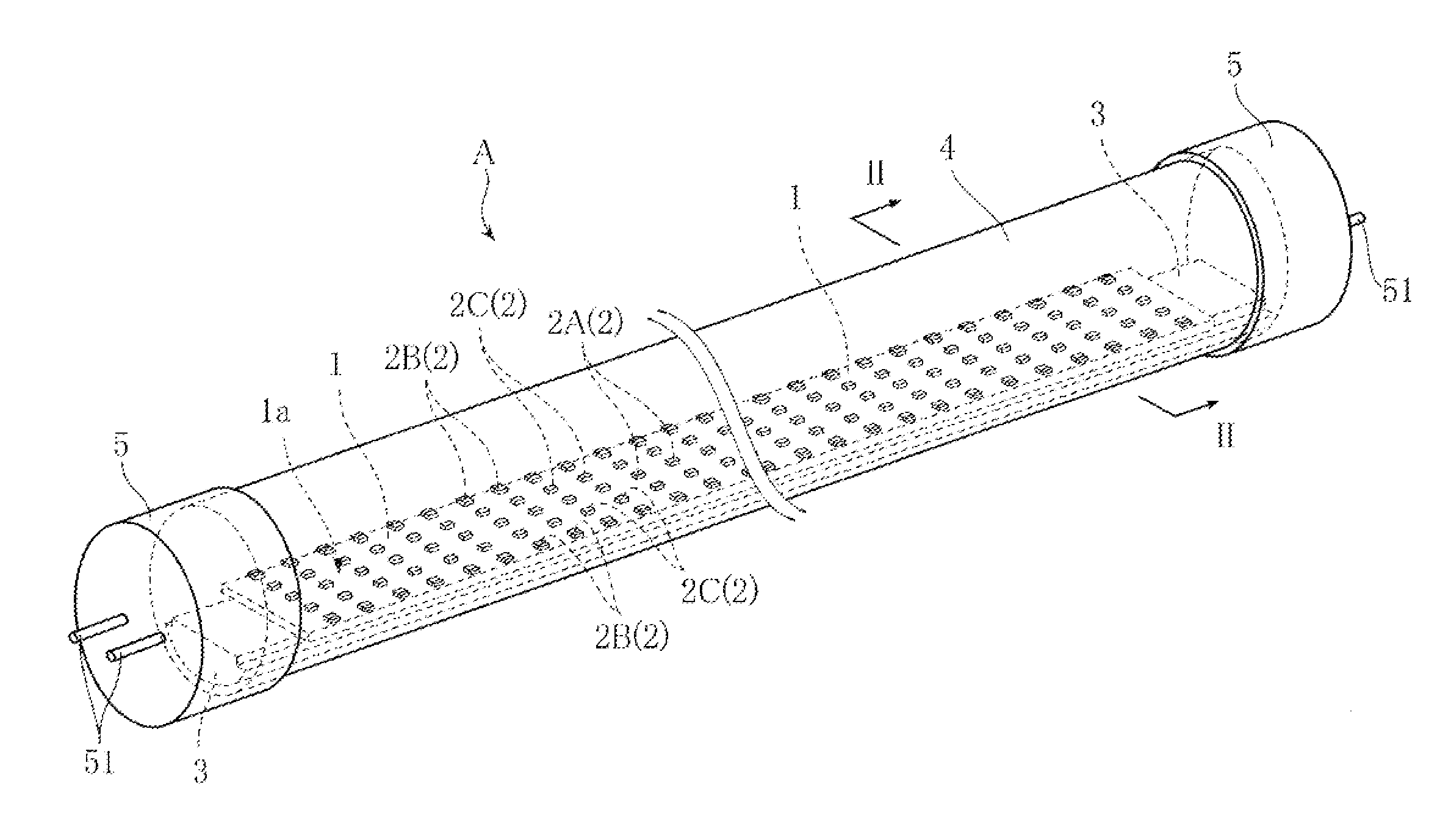
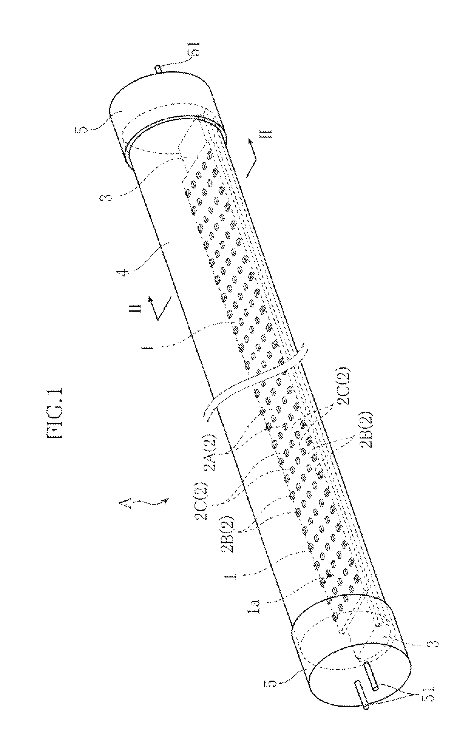
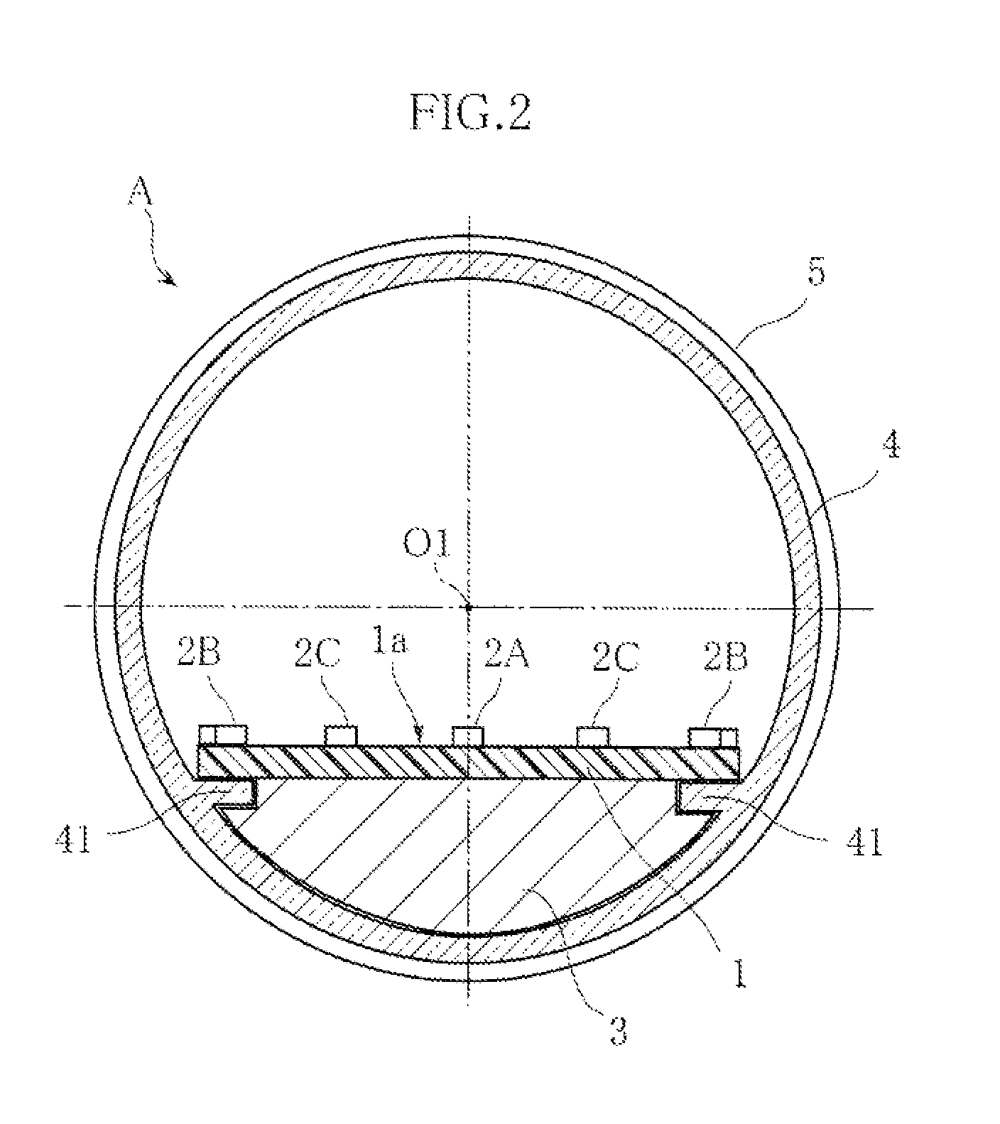
[0093]FIGS. 1 and 2 show an example of LED lamp according to the present invention. FIG. 1 is a schematic perspective view of the LED lamp, whereas FIG. 2 is a schematic sectional view taken along lines II-II in FIG. 1.

[0094]The LED lamp A of this embodiment includes a support substrate 1, a plurality of LED modules 2, a heat dissipation member 3, a case 4 and a pair of bases 5. The LED lamp A is to be used as attached to a general-use fluorescent lighting fixture, as a substitute for e.g. a straight-tube fluorescent lamp. When the general-use fluorescent lighting fixture is attached to e.g. an indoor ceiling, the LED lamp A is usually mounted to the lighting fixture in such a manner that the main light emission direction of the LED modules 2 is oriented downward.

[0095]The support substrate 1 supports the LED modules 2. The support substrate 1 is made of e g glass-fib...


PUM


Abstract

An LED lamp A includes a plurality of LED modules 2 each including an LED chip 21, and a support member 1 including a support surface 1a on which the LED modules 2 are mounted. The LED modules 2 include a plurality of kinds of LED modules, or a first through a third LED modules 2A, 2B and 2C different from each other in directivity characteristics that represent light intensity distribution with respect to light emission directions. This arrangement ensures that the entire surrounding area can be illuminated with sufficient brightness.

Description

TECHNICAL FIELD[0001]The present invention relates to an LED lamp that uses a light emitting diode (hereinafter referred to as “LED”) as the light source.BACKGROUND ART[0002]FIG. 63 shows an example of conventional LED lamp (see Patent Document 1, for example). The LED lamp X shown in the figure includes a plate-like substrate 91, a plurality of LED modules 92 mounted on the substrate 91, a heat dissipation member 95 attached to the substrate 91, a case 93 accommodating the substrate 91, and terminals 94. The substrate 91 is provided with a wiring pattern, not shown, connected to the LED modules 92 and the terminal 94. The LED lamp X is structured such that the LED modules 92 can be turned on when the terminals 94 are fitted into inlet ports of a socket of a general-use fluorescent lighting fixture.[0003]The general-use fluorescent lighting fixture herein refers to lighting fixtures widely used for interior lighting as the main application, and more specifically, lighting fixtures w...

Claims


Application Information

Patent Timeline
IPC IPC(8): H01L33/64
CPCF21K9/17F21Y2101/02H01L33/54H01L33/58H01L33/60F21Y2105/001H01L2224/48227H01L2224/48091H01L2924/01021H01L2924/00014F21Y2105/10F21Y2103/10F21Y2115/10F21K9/68F21K9/27H01L25/0753H01L33/62F21K9/233
Inventor KAWABATA, YUSAKU
Owner ROHM CO LTD
Why Eureka
Try Eureka