Optical sheet member and display device
a technology of optical sheet and display device, which is applied in the field of optical sheet member and display device, can solve the problems of specific studies in respect, which have not been conducted, and achieve the effect of improving front brightness and color reproduction rang
- Summary
- Abstract
- Description
- Claims
- Application Information
AI Technical Summary
Benefits of technology
Problems solved by technology
Method used
Image
Examples
embodiment (
ii)
Wavelength Selective Reflective Polarizer
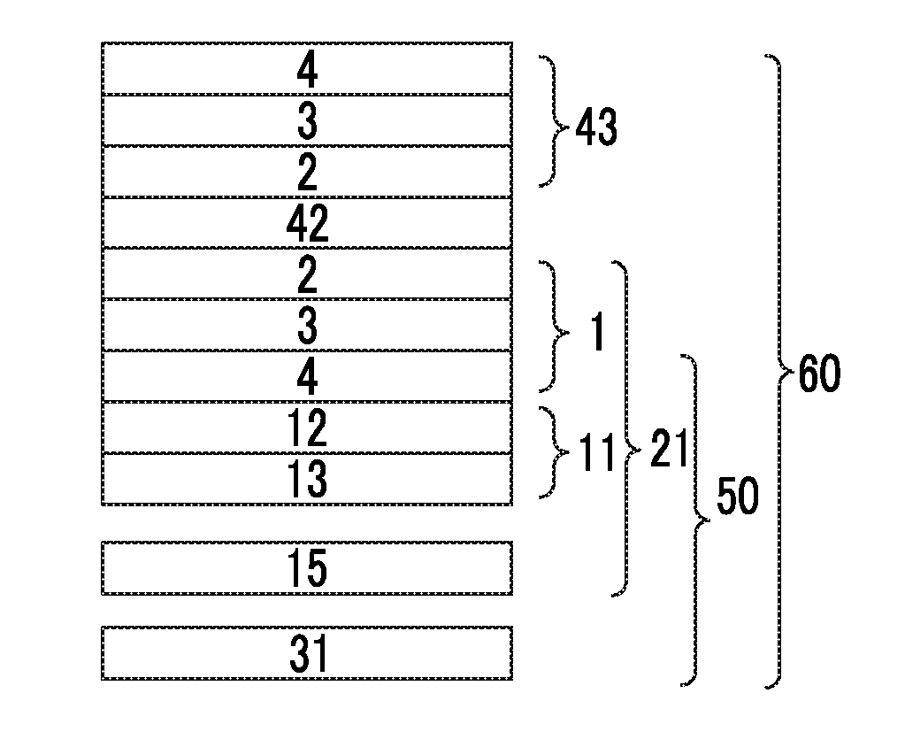
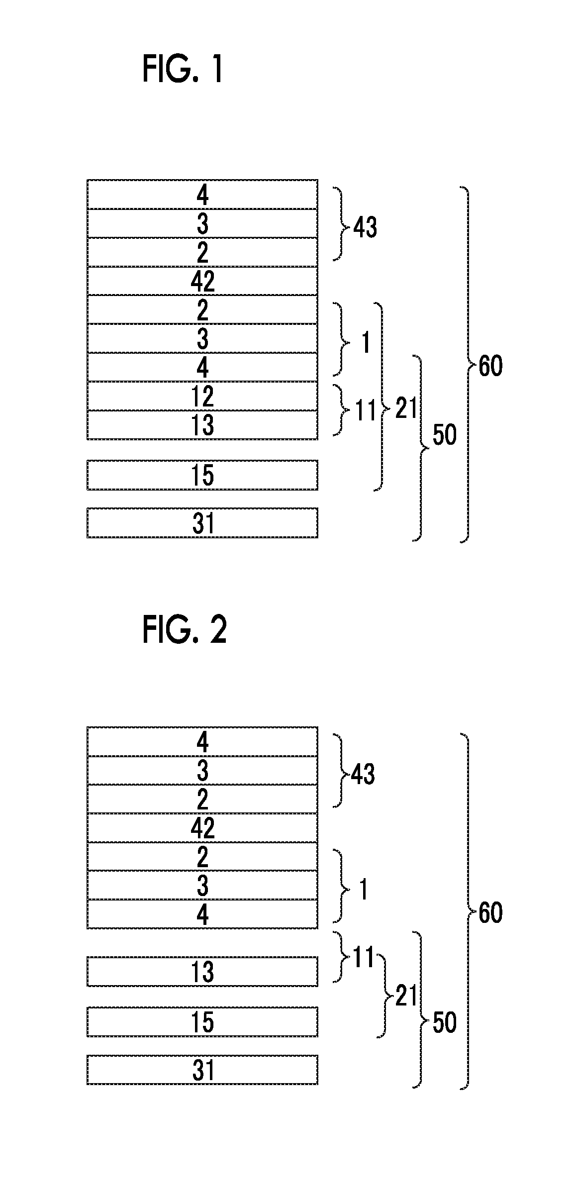
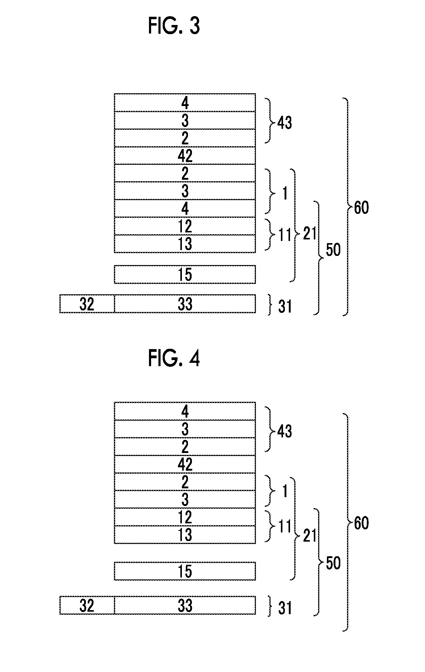
[0356]Next, the embodiment (ii) will be described. Examples of the wavelength selective reflective polarizer of the embodiment (ii) are able to include a multi-layer film in which a plurality of layers having different refractive indices are laminated. The layer configuring the multi-layer film may be an inorganic layer, or may be an organic layer. For example, a dielectric multi-layer film configured by sequentially laminating materials having different refractive indices (a high refractive index material and a low refractive index material) is able to be preferably used. Further, a metal / dielectric multi-layer film in which a metal film is added to the configuration of the dielectric multi-layer film may be used. Furthermore, the multi-layer film described above is able to be formed by sedimenting a plurality of film formation materials on a substrate using a known film formation method such as electron beam (EB) vapor deposition and spu...
manufacturing example 1
Preparation of Polarizing Plate
[0525]A commercially available cellulose acylate-based film “TD60” (manufactured by Fujifilm Corporation) was prepared as a front-side polarizing plate protective film of a backlight side polarizing plate.
[0526]A commercially available cellulose acylate-based film “TD60” (manufactured by Fujifilm Corporation) was used as a rear-side polarizing plate protective film of the backlight side polarizing plate.
[0527]A polarizer was manufactured by the same method as that in [0219] to [0220] of JP2006-293275A, the retardation film and the polarizing plate protective film described above were bonded to both surfaces of the polarizer, and thus, a polarizing plate was manufactured. In addition, the polarizing plate protective film on one surface may function as a λ / 4 layer, and the polarizing plate protective film on one surface is able to be omitted from the viewpoint of reducing the thickness.
manufacturing example 2
Preparation of Polarizing Plate
[0528]A retardation film and a polarizing plate protective film were respectively bonded to both surfaces of a polarizer, and thus, a polarizing plate was manufactured by the same method as that in Manufacturing Example 1 except that a long film 1 having a thickness of 40 μm, which was formed by supplying a pellet of a mixture having Tg of 127° C. of 90 parts by mass of an acrylic resin having a lactone ring structure {Copolymerization Monomer Mass Ratio=Methyl Methacrylate / Methyl 2-(Hydroxy Methyl) Acrylate=8 / 2, a lactone cyclization rate of approximately 100%, a content ratio of the lactone ring structure of 19.4%, a weight average molecular weight of 133000, a melt flow rate of 6.5 g / 10 minutes (240° C., 10 kgf), Tg of 131° C.} and 10 parts by mass of an acrylonitrile-styrene (AS) resin {TOYO AS AS20, manufactured by TOYO STYRENE Co., Ltd.} to a biaxial extruder, and by performing melting extrusion at a temperature of approximately 280° C. into the ...
PUM
 Abstract
Description
Claims
Application Information
 - R&D
- Intellectual Property
- Life Sciences
- Materials
- Tech Scout
- Unparalleled Data Quality
- Higher Quality Content
- 60% Fewer Hallucinations
Browse by: Latest US Patents, China's latest patents, Technical Efficacy Thesaurus, Application Domain, Technology Topic, Popular Technical Reports.
© 2025 PatSnap. All rights reserved.Legal|Privacy policy|Modern Slavery Act Transparency Statement|Sitemap|About US| Contact US: help@patsnap.com


