Display device with optical input function

a display device and optical input technology, applied in the field of display devices with optical input functions, can solve the problems of reducing the circuit scale of the ic, and reducing the manufacturing yield, so as to increase the circuit scale, and reduce the cost of the external ic.

Inactive Publication Date: 2006-02-16
JAPAN DISPLAY CENTRAL CO LTD
View PDF6 Cites 60 Cited by
  • Summary
  • Abstract
  • Description
  • Claims
  • Application Information

AI Technical Summary

Benefits of technology

[0014] (A2) An object of the embodiments is to provide a display device having an optical input function in which portions partially lost due to dot-form defects or line-form defects are compensated for, an increase in the circuit scale and a rise in the cost of the external IC are suppressed and the manufacturing yield is increased.
[0015] (B2) An object of the embodiments is to provide a display device having an optical input function which can adequately determine light input / non-input (or contact / non-contact state) without attaching a switch which determines the contact / non-contact state to a light source.
[0016] (C2) Further, an object of the embodiments is to provide a display device having an optical input function which can compensate for portions which are partially lost due to the presence of dot-form defects or line-form defects and adequately determine light input / non-input (or contact / non-contact).

Problems solved by technology

In order to perform the image processing operation, it is generally required to provide a memory with a storage capacity corresponding to several lines of image data in the IC, and therefore, there occurs a problem that the circuit scale of the IC becomes large and the cost thereof becomes high.
As a result, there occurs a problem that the manufacturing yield is lowered.
Further, in the display device having the optical input function, for example, when coordinates are input by illumination by use of a light source such as a light pen, there occurs a problem that it is difficult to determine whether or not the tip end of the pen is set in contact with the display screen since the light source is always kept ON.
However, with this method, it is difficult to realize smoothly writing feelings.

Method used


Image

  • Display device with optical input function
  • Display device with optical input function
  • Display device with optical input function

Examples


second embodiment

[0099] Next, this invention is explained. In a circuit shown in FIG. 12, a median filter circuit in a particular case of a rank order filter circuit (in a case wherein the rank value r is set to “5” in the rank order filter circuit for the neighboring 3×3 pixels) is used as a filter 152. In this case, the same operation can be performed by changing the rank value r in the rank order filter circuit described before, but it can be attained by use of a simplified circuit configuration. FIG. 12 shows an example of the circuit configuration.

[0100] Only the circuit portion of the filter 152 shown in FIG. 12 is different from that of FIG. 8. Each of sort circuits SORT3 is a combinational circuit which sorts three input values in an ascending order and outputs the same and each of sort circuits SORT2 is a combinational circuit which sorts two input values in an ascending order and outputs the same. The sort circuit SORT3 and sort circuit SORT2 output signals in response to inputs as shown i...

third embodiment

[0105] Next, this invention is explained. FIG. 14 is a block diagram showing one example of the embodiment in which the filter process is serially performed.

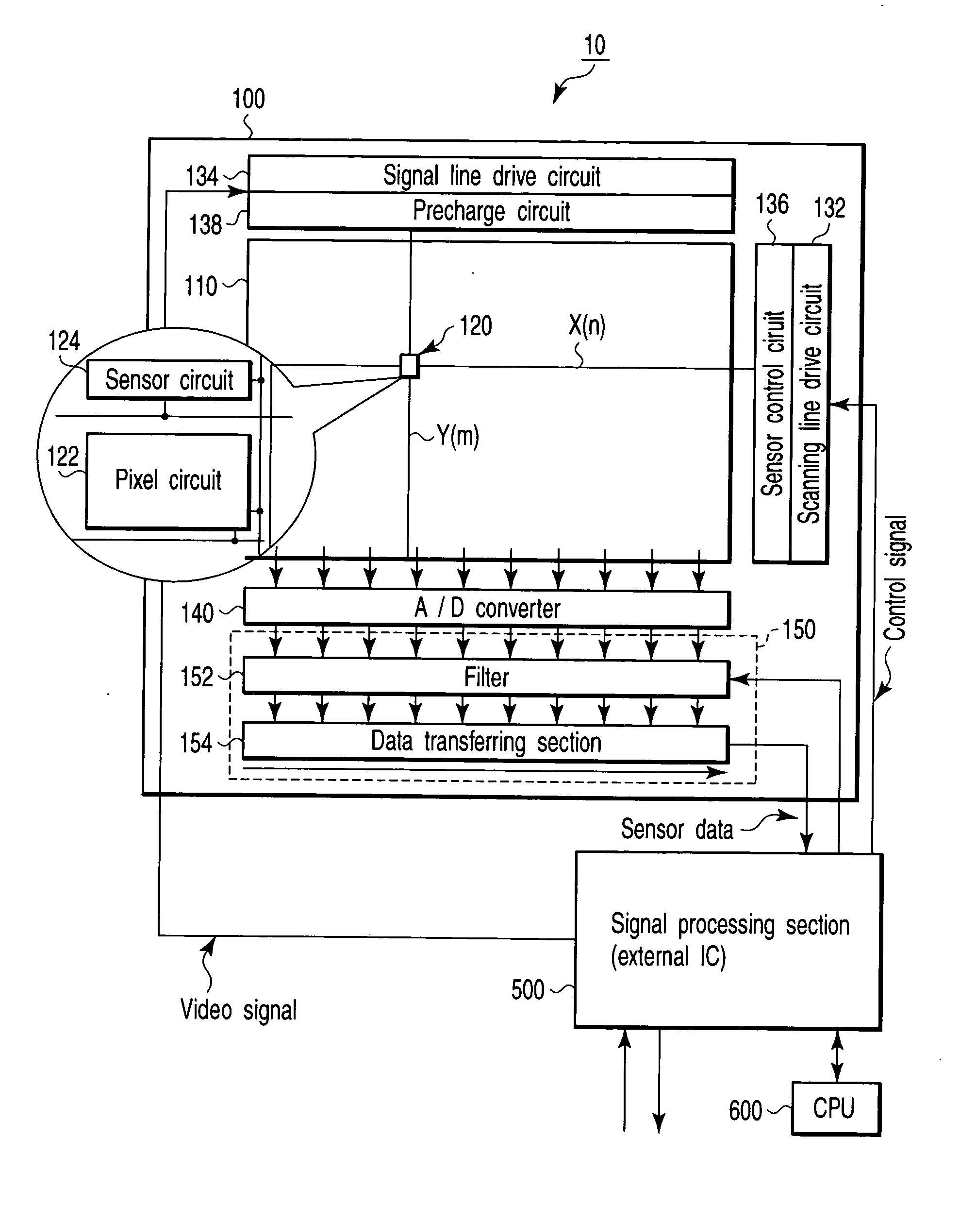
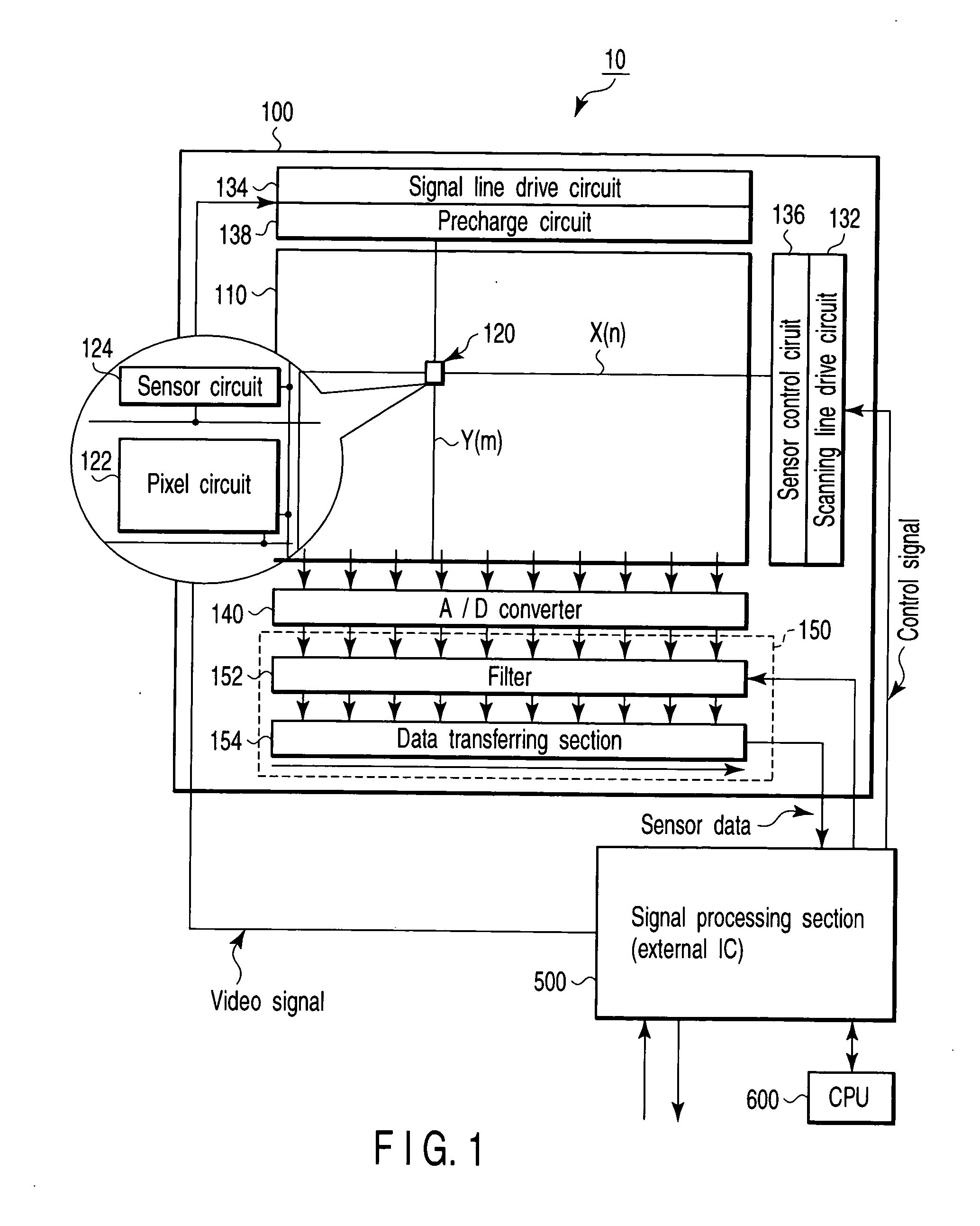
[0106] In the present embodiment, an output processing section 150 includes a data transferring section 154 which serially outputs data of pixels of three rows. Analog signals output from sensor circuits 124 are converted into digital image data by an A / D converter 140 and input to the output processing section 150. In the output processing section 150, digital image data transferred by the data transferring section 154 of three rows are serially subjected to a filter process in the filter 152 connected to the final stage of the output processing section 150 and output to the exterior.

[0107]FIG. 15 shows an example of the circuit configuration when a rank order filter is used as the filter 152, for example. Delay flip-flops D-FF4 configure a shift register which transfers data in the right direction in the drawing in response t...


PUM


Abstract

A display device includes a plurality of scanning lines, a plurality of signal lines, a plurality of pixel circuits and sensor circuits, a signal line drive circuit and scanning line drive circuit which drive the plurality of pixel circuits, and a precharge circuit and sensor control circuit which drive the sensor circuits. A filter subjects image data to an interpolation process to compensate for a gradation value of an output. In a signal processing section, the area of a light receiving area is calculated and it is determined that a light source is set in contact with a display screen.

Description

CROSS-REFERENCE TO RELATED APPLICATIONS [0001] This application is based upon and claims the benefit of priority from prior Japanese Patent Applications No. 2004-233459, filed Aug. 10, 2004; and No. 2005-062891, filed Mar. 7, 2005, the entire contents of both of which are incorporated herein by reference.BACKGROUND OF THE INVENTION [0002] 1. Field of the Invention [0003] This invention relates to a display device with an optical input function which can input information by, for example, causing light from a light source such as a light pen to illuminate the display screen. With the display device, illuminated position information or contact position information on the display screen illuminated by the light is detected. More specifically, this invention is made clearer by explaining embodiments to be described later. [0004] 2. Description of the Related Art [0005] Recently, a liquid crystal display device is widely used as a display device for various equipment such as a mobile tel...

Claims


Application Information

Patent Timeline
Patent Type & Authority Applications(United States)
IPC IPC(8): G09G5/00G06F3/041
CPCG06F3/042G06F3/0412G09G3/36G02F1/13G09G3/20
Inventor YOSHIDA, MASAHIRONAKAMURA, TAKASHINAGAOKA, KAZUTAKA
Owner JAPAN DISPLAY CENTRAL CO LTD
Why Eureka
Try Eureka