Cleaner head for a vacuum cleaner

a vacuum cleaner and cleaner head technology, applied in the direction of suction cleaners, cleaning equipment, suction nozzles, etc., can solve the problems of increasing the cost, size and/or weight of the cleaner head, increasing the flow of clean air through the turbine, and affecting the cleaning effect of the cleaning head, etc., to achieve the effect of compact arrangement and unwanted noise or vibration

Inactive Publication Date: 2014-02-13
DYSON TECH LTD
View PDF4 Cites 5 Cited by
  • Summary
  • Abstract
  • Description
  • Claims
  • Application Information

AI Technical Summary

Benefits of technology

[0013]When the baffle moves to the closed position, one or more small gaps may exist between the baffle and a wall of the second airflow path. As the second airflow is drawn through these gaps, unwanted noise or vibration may be generated. The baffle may therefore comprise a flexible seal that deforms to create a seal within the second airflow path when in the closed position. As a result, such gaps may be avoided or minimised.
[0014]The baffle may comprise a body to which the seal is attached. The body is then made of a stiffer material than that of the seal. For example, the body may be formed of a thermoplastic, whilst the seal may be formed of natural or synthetic rubber which is overmoulded onto the body. During use, suction at the

Problems solved by technology

However, should the path carrying the dirty air become obstructed, the flow of clean air through the turbine will increase.
As a result, components of the driv

Method used


Image

  • Cleaner head for a vacuum cleaner
  • Cleaner head for a vacuum cleaner
  • Cleaner head for a vacuum cleaner

Examples


Embodiment Construction

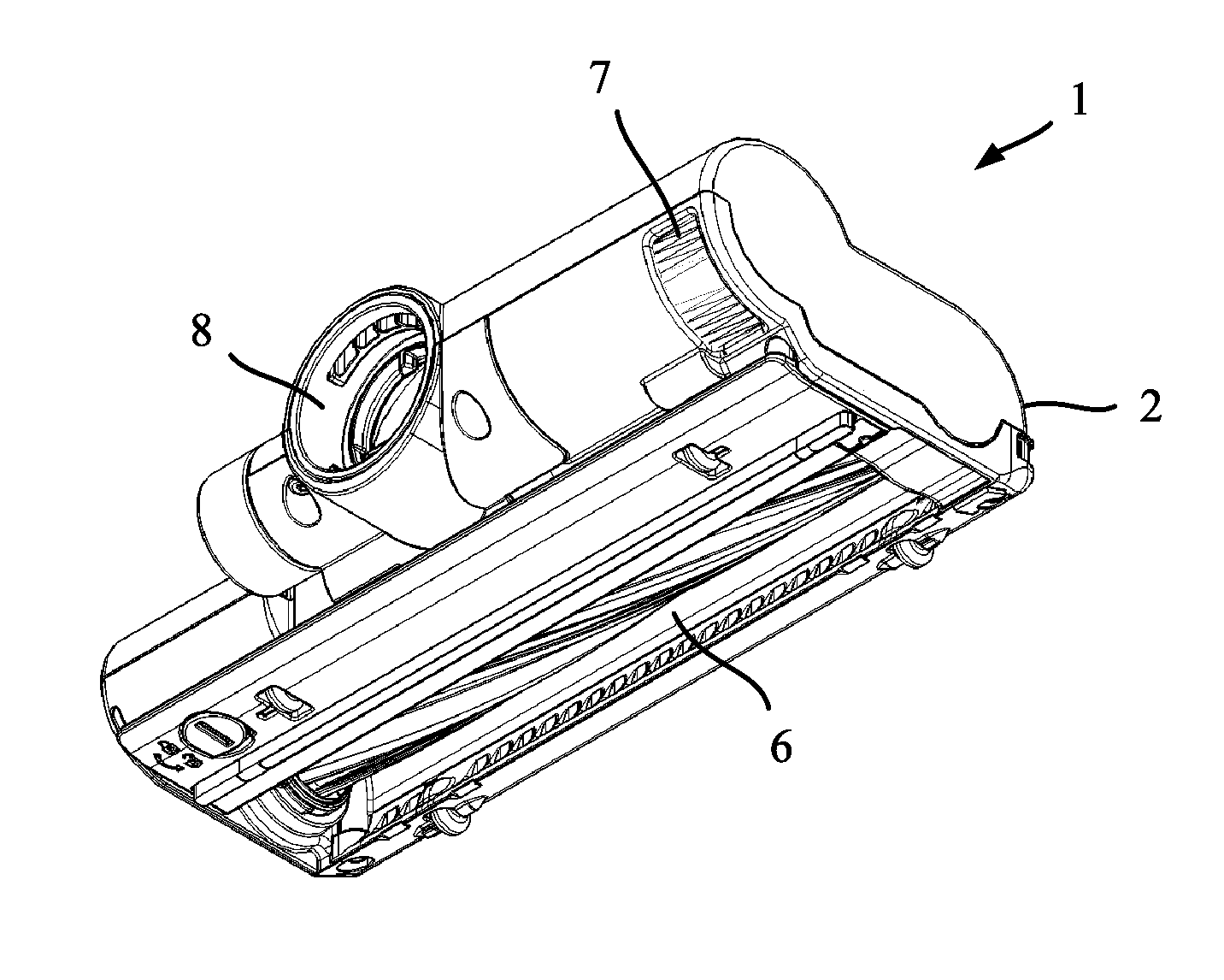
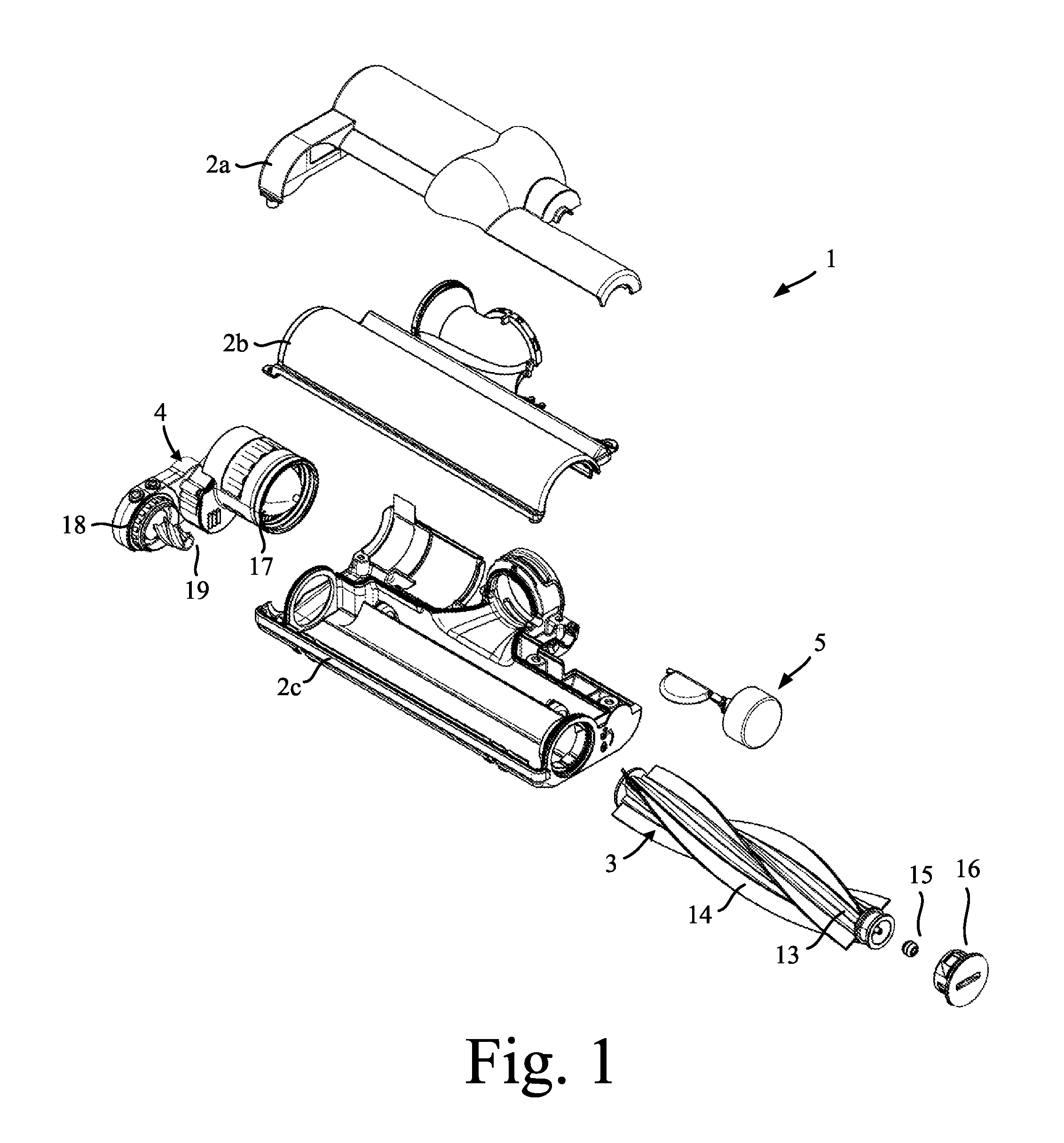
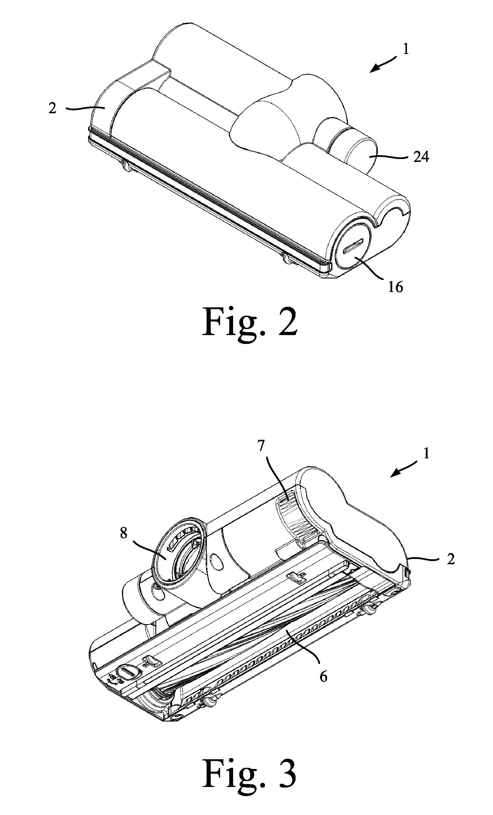
[0032]The cleaner head 1 of FIGS. 1 to 8 comprises a housing 2, an agitator 3, a drive assembly 4, and a drive-control mechanism 5.

[0033]The housing 2 comprises several different sections 2a-2c that, when assembled, define a suction inlet 6, a turbine inlet 7, an outlet 8, a first airflow path 9 for carrying a first airflow from the suction inlet 6 to the outlet 8, and a second airflow 10 path for carrying a second airflow from the turbine inlet 7 to the outlet 8

[0034]The suction inlet 6 is formed on an underside of the housing 2. During use, dirty air is drawn in through the suction inlet 6 and carried by the first airflow path 9 to the outlet 8.

[0035]The turbine inlet 7 is formed at the rear of the housing 4. Owing to its location, clean air rather than dirty air is drawn in through the turbine inlet 7 during operation. From there, the clean air is carried by the second airflow path 10 to the outlet 8.

[0036]The first and second airflow paths 9,10 are defined by walls of the housin...


PUM


Abstract

A cleaner head that includes a suction inlet for admitting a first airflow, a turbine inlet for admitting a second airflow, an outlet for discharging the first airflow and the second airflow and an agitator and its drive assembly. A first airflow path then carries the first airflow from the suction inlet to the outlet, and a second airflow path carries the second airflow from the turbine inlet to the outlet. The drive assembly includes a turbine that is driven by the second airflow. A baffle is located in the second airflow path and is movable between an open position in which the second airflow path is unrestricted and a closed position in which the second airflow path is restricted. The baffle is biased in the open position and moves to the closed position when the dynamic pressure of the second airflow at the baffle exceeds a threshold.

Description

REFERENCE TO RELATED APPLICATIONS[0001]This application claims the priority of United Kingdom Application No. 1214420.0, filed Aug. 13, 2012, the entire contents of which are incorporated herein by reference.FIELD OF THE INVENTION[0002]The present invention relates to a cleaner head for a vacuum cleaner.BACKGROUND OF THE INVENTION[0003]The cleaner head of a vacuum cleaner typically comprises an agitator driven by a drive assembly. The drive assembly may include a turbine for generating the torque necessary to drive the agitator. The turbine may be driven by dirty air that is drawn in through the main suction inlet. Alternatively, the turbine may be driven by clean air that is drawn in through an inlet distinct from the suction inlet.[0004]A clean-air turbine has the advantage that the turbine is not exposed to the dirty air, which might otherwise obstruct the turbine. However, should the path carrying the dirty air become obstructed, the flow of clean air through the turbine will in...

Claims


Application Information

Patent Timeline
IPC IPC(8): A47L9/04
CPCA47L9/0416A47L9/0427
Inventor COLEMAN, JAMES MARTINCROSS, SIMON PETER
Owner DYSON TECH LTD
Why Eureka
Try Eureka