Liquid container and liquid ejection system

a liquid ejection system and liquid container technology, applied in printing and other directions, can solve the problems of affecting the original function affecting the ejection effect of the sheet member, and not preventing the leakage of ink, so as to reduce the probability of leakage and lower the air permeability of the sheet member

Inactive Publication Date: 2014-05-29
SEIKO EPSON CORP
View PDF2 Cites 37 Cited by
  • Summary
  • Abstract
  • Description
  • Claims
  • Application Information

AI Technical Summary

Benefits of technology

[0011]When the open-air hole is covered with a sheet member having gas-liquid separation function, the sheet member may be wetted with ink overflowing from the open-air hole. The sheet member wetted with ink may impair the original function of the sheet member. For example, the sheet member wetted with ink may not prevent leakage of ink through the sheet member to the outside. For example, the sheet member wetted with ink may lower the air permeability of the sheet member and may interfere with introduction of the air from the open-air hole into the ink tank. This problem is not characteristic of the ink tank but is commonly found in the liquid container which stores liquid to be ejected from the liquid ejection apparatus, and is designed to have the liquid inlet separately from the open-air hole.
[0124]The liquid ejection system according to the nineteenth aspect provides the liquid ejection system including the liquid container according to any one of the first through the eighteenth aspects. In one example, the liquid ejection system including the liquid container according to any one of the first through the sixth aspects provides the liquid ejection system including the liquid container having the lowered probability that the liquid overflows from the open-air hole during filling of the liquid. In another example, the liquid ejection system including the liquid container according to any one of the seventh through the ninth aspects provides the liquid ejection system having the lowered probability of trouble occurring due to invasion of the air into the liquid ejection apparatus. In still another example, the liquid ejection system including the liquid container according to any one of the tenth through the thirteenth aspects and the fifteenth aspect dependent on the thirteenth aspect provides the liquid ejection system that enables the liquid level in the liquid container exposed to the atmosphere to be maintained in a preset height range from the mounting surface even in the use attitude immediately after filling of the liquid. This keeps the height difference between the head and the liquid level exposed to the atmosphere within a preset range, thus ensuring stable ejection of the liquid from the head. In another example, the liquid ejection system including the liquid container according to any one of the fourteenth aspect and the fifteenth aspect dependent on the fourteenth aspect provides the liquid ejection system including the liquid container that enables the liquid level in the liquid chamber to be readily checked in each of the use attitude and the filling attitude. In still another example, the liquid ejection system including the liquid container according to any one of the sixteenth through the eighteenth aspects provides the liquid ejection system including the liquid container having the lowered probability that the bubbles generated during filling of the liquid overflow from the liquid inlet.

Problems solved by technology

Additionally, the user may be unaware of the overflow of ink from the open-air hole.
The sheet member wetted with ink may impair the original function of the sheet member.
For example, the sheet member wetted with ink may not prevent leakage of ink through the sheet member to the outside.
For example, the sheet member wetted with ink may lower the air permeability of the sheet member and may interfere with introduction of the air from the open-air hole into the ink tank.
This problem is not characteristic of the ink tank but is commonly found in the liquid container which stores liquid to be ejected from the liquid ejection apparatus, and is designed to have the liquid inlet separately from the open-air hole.
Invasion of the air into the head may cause failure of printing, such as missing dots.
This problem is not characteristic of the ink tank but is commonly found in the liquid container for supplying liquid to the liquid ejection apparatus, which is designed to enable the liquid to be filled through the liquid inlet into the liquid container.
Various failures and troubles may arise when ink is refilled through the liquid inlet into the ink tank and the ink is supplied from the ink tank to the printer.
When the ink tank is filled with ink and the ink supply from the ink tank to the recording head is resumed, the atmosphere-exposed liquid level may not be maintained in the preset height range, which results in unstable supply of ink from the ink tank to the recording head.
For example, the atmosphere-exposed liquid level may be located above the recording head, which may cause leakage of ink from the recording head by the pressure applied by the ink tank (liquid pressure).
This problem is not characteristic of the ink tank but is commonly found in the liquid container for storing the liquid, which is to be ejected from the liquid ejection apparatus, which is designed to include the liquid inlet for filling the liquid.
When ink filling continues in the presence of bubbles, bubbles may overflow from the ink inlet.
This problem is not characteristic of the ink tank but is commonly found in the liquid container for storing the liquid, which is to be ejected from the liquid ejection apparatus, which is designed to include the liquid inlet for filling the liquid.
When the use attitude is different from the filling attitude, the user may have difficulty in checking the amount of ink remaining in the ink tank in the respective attitudes.
This problem is not characteristic of the ink tank but is commonly found in the liquid container for storing the liquid, which is to be ejected from the liquid ejection apparatus, which is designed to include the liquid inlet for filling the liquid.
This results in preventing the sheet member from being wetted with the liquid during filling of the liquid and lowering the probability that the function of the sheet member is damaged.
This results in further lowering the probability that the liquid overflows from the open-air hole during filling of the liquid.
This results in lowering the probability that the quality of the liquid is lowered by, for example, contamination of the liquid with part of the plug member as impurity.
This lowers the probability of trouble occurring during filling of the liquid.

Method used


Image

  • Liquid container and liquid ejection system
  • Liquid container and liquid ejection system
  • Liquid container and liquid ejection system

Examples


first embodiment

B-1. First Embodiment

B-1-1. Structure of Liquid Ejection System

[0162]FIGS. 3A and 3B are explanatory diagrams showing a liquid ejection system 1 according to a first embodiment. FIG. 3A is a perspective view showing the appearance of the liquid ejection system 1. FIG. 3B is a perspective view showing the appearance of the liquid ejection system 1 with liquid containers 30 according to the first embodiment.

[0163]Referring to FIG. 3A, the liquid ejection system 1 includes an inkjet printer 12 (also called “printer 12”) as a liquid ejection apparatus and a tank unit 50. The printer 12 includes a sheet feed assembly 13, a sheet discharge assembly 14, a carriage 16 and four sub-tanks 20. The four sub-tanks 20 respectively store different color inks. More specifically, the four sub-tanks 20 include a sub-tank 20Bk for storing black ink, sub-tank 20Cn for storing cyan ink, a sub-tank 20Ma for storing magenta ink and a sub-tank 20Yw for storing yellow ink. The four sub-tanks 20 are mounted ...

second embodiment

B-2. Second Embodiment

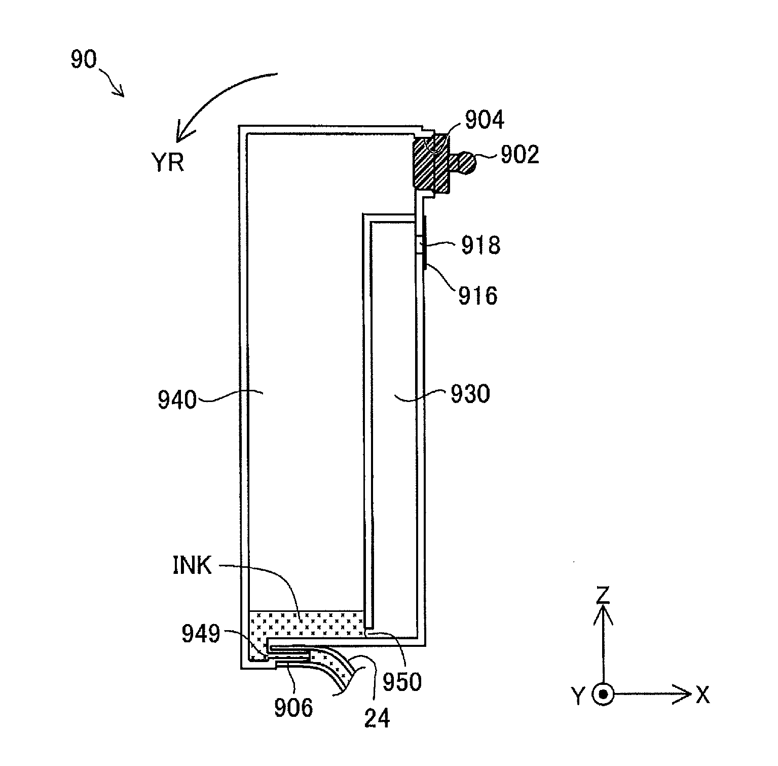
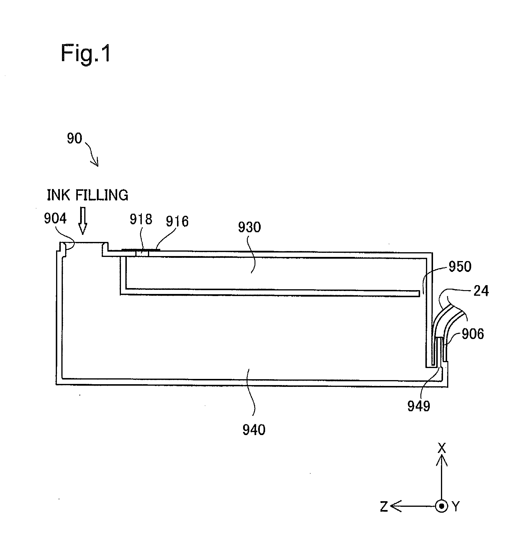
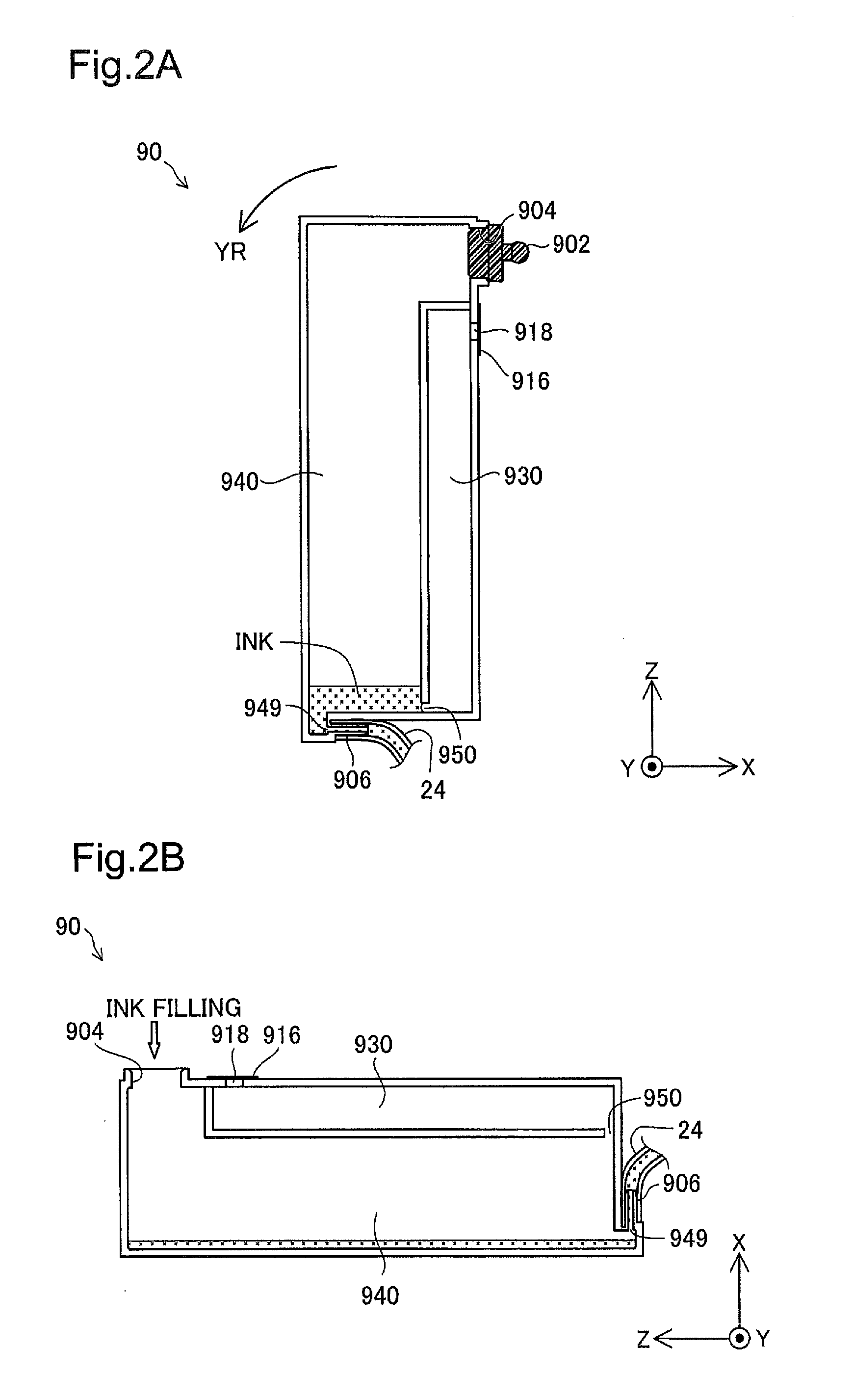
[0216]FIGS. 14A and 14B are explanatory diagrams showing an ink tank 30a according to a second embodiment. FIGS. 14A and 14B are the view corresponding to FIG. 11A of the first embodiment. FIG. 14A illustrates the structure of the ink tank 30a of the second embodiment. FIG. 14B illustrates the state of the ink tank 30a when an excess amount of ink is filled. The differences from the ink tank 30 of the first embodiment are the structure of a liquid chamber 340a and the height of a liquid inlet 304a in the filling attitude. Otherwise the structures of the second embodiment are similar to those of the first embodiment and are thus expressed by the like numerals and symbols and are not specifically described here. Like the ink tank 30 of the first embodiment, the ink tank 30a of the second embodiment is used for the liquid ejection system 1 (FIGS. 3A and 3B). For the better understanding, a plug member 302 is shown by the broken line in FIG. 14A.

[0217]As shown in F...

third embodiment

B-3. Third Embodiment

[0223]FIG. 16 is an explanatory diagram showing an ink tank 30b according to a third embodiment. FIG. 16 is the view corresponding to FIGS. 11A and 14A of the above embodiments. The differences from the first embodiment are the structure of a connection path 350b and the structure of a liquid retainer 345b. Otherwise the structures of the third embodiment are similar to those of the first embodiment and are thus expressed by the like numerals and symbols and are not specifically described here.

[0224]The ink tank 30b of the third embodiment has the connection path 350b provided in the form of an aperture instead of the elongated flow path. The connection path 350b has an opening area sufficient to form the meniscus. Additionally, a porous member 345b is provided to close one end 349 in the liquid chamber 340. This porous member 345 serves as the liquid retainer to retain a certain amount of ink. The porous member 345b forms an inner through-path to enable ink in ...


PUM


Abstract

A liquid container for supplying a liquid to a liquid ejection apparatus comprises: a liquid chamber provided to store the liquid; an air chamber connected with the liquid chamber to introduce the outside air into the liquid chamber with consumption of the liquid in the liquid chamber; an open-air hole provided to introduce the outside air into the air chamber; and a liquid inlet provided to fill the liquid into the liquid chamber, wherein the liquid inlet is located at a lower position than the open-air hole, in a filling attitude of the liquid container in which the liquid is filled into the liquid chamber.

Description

CROSS REFERENCE TO RELATED APPLICATIONS[0001]This application is a continuation application of U.S. patent application Ser. No. 13 / 212,921, filed on Aug. 18, 2011, which claims priority to Japanese Patent Application No. 2010-160358, filed on Jul. 15, 2010, Japanese Patent Application No. 2010-160361, filed on Jul. 15, 2010, Japanese Patent Application No. 2010-197272, filed on Sep. 3, 2010, Japanese Patent Application No. 2010-197274, filed on Sep. 3, 2010, Japanese Patent Application No. 2010-197275, filed on Sep. 3, 2010, and International Patent Application No. PCT / JP2011 / 003715, filed on Jun. 29, 2011, each of which is incorporated herein by reference.BACKGROUND[0002]1. Technical Field[0003]The present invention relates to a liquid container and a liquid ejection system including a liquid container.[0004]2. Related Art[0005]A printer as one example of liquid ejection apparatus causes ink to be ejected from a recording head (also called “head”) onto a recording object (for examp...

Claims


Application Information

Patent Timeline
Patent Type & Authority Applications(United States)
IPC IPC(8): B41J2/175
CPCB41J2/175B41J2/17513B41J2/1752B41J2/17523B41J2/17553B41J2/19B41J2/17506
Inventor SHIMIZU, YOSHIAKIISHIZAWA, TAKUTAKEDA, YUKIKOGANEHIRA, SHUICHI
Owner SEIKO EPSON CORP
Why Eureka
Try Eureka