Thin Keyboard

a keyboard and keyboard technology, applied in the field of input devices, can solve the problems of pantograph type keyboard and limitation of the application of thin laptop pcs, and achieve the effect of increasing distan

Active Publication Date: 2014-06-19
LENOVO PC INT
View PDF11 Cites 15 Cited by
  • Summary
  • Abstract
  • Description
  • Claims
  • Application Information

AI Technical Summary

Benefits of technology

[0016]In accordance with a preferred embodiment of the present invention, an input device includes a key located in a ready position by means of magnets. The input device has the key with a key magnet mounted therein, and a holding magnet for locating the key in the ready position by a magnetic attraction to the key magnet. A release mechani

Problems solved by technology

Then, when the travel distance becomes further longer, the top of the rubber dome that has just reached a yield point gets dented suddenly, resulting in a drop in reaction force.
Ho

Method used


Image

  • Thin Keyboard
  • Thin Keyboard
  • Thin Keyboard

Examples


Embodiment Construction

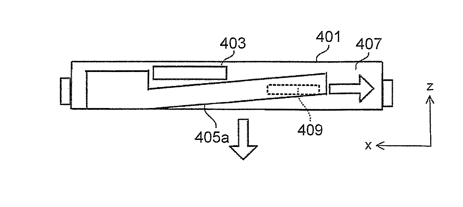
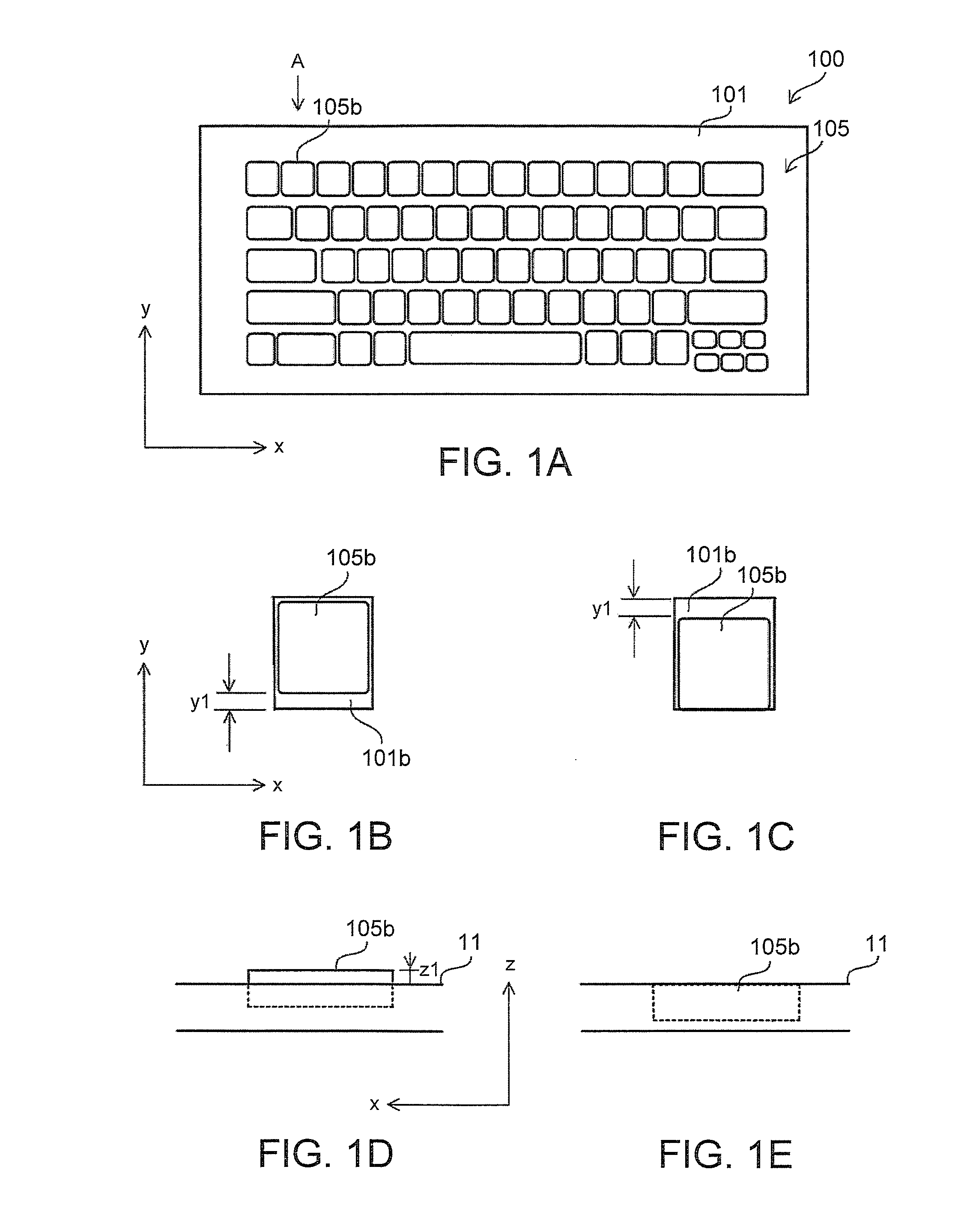
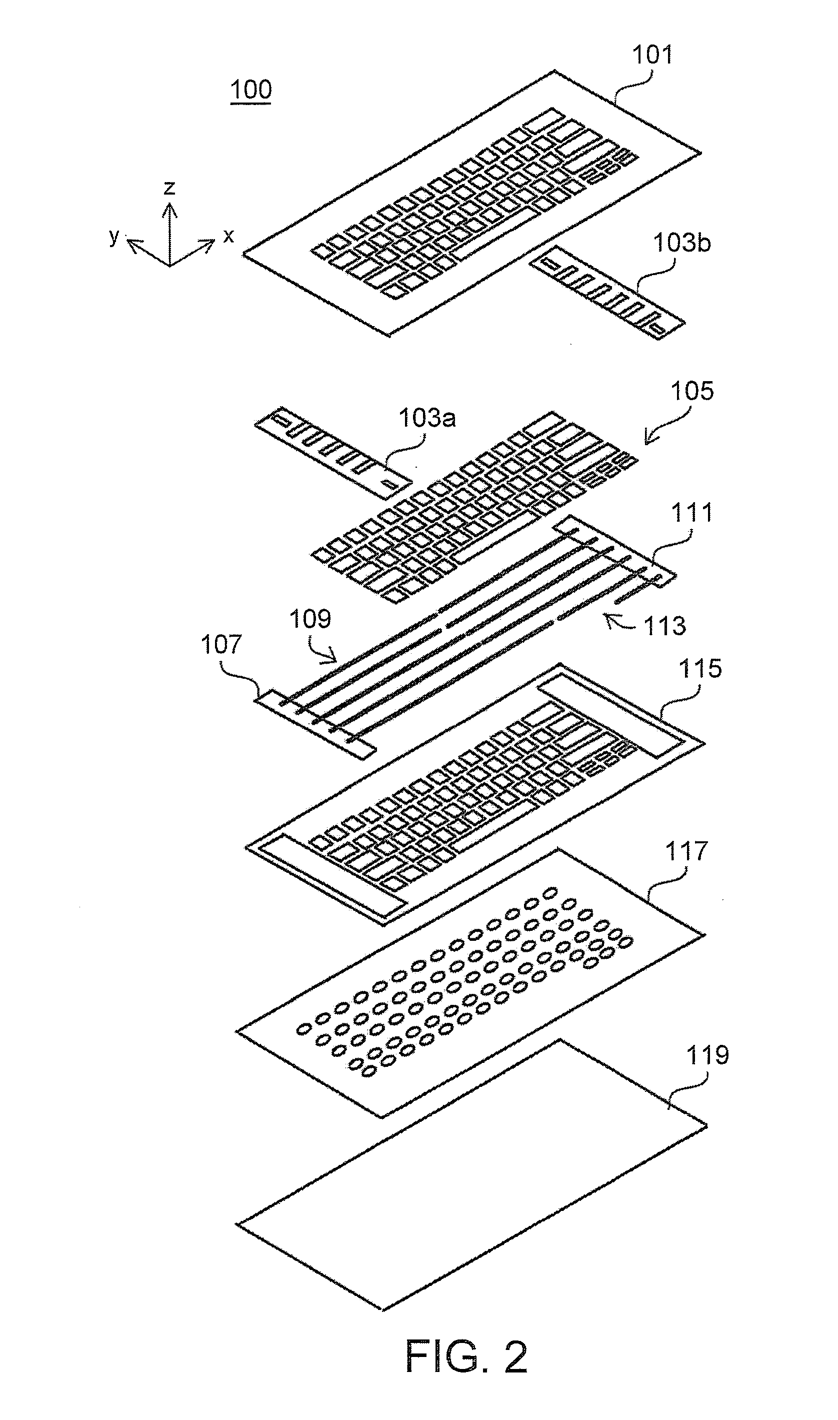
[0038]FIG. 1 is a diagram for describing an outline of an oblique slide-type keyboard (hereinafter, simply referred to as the keyboard) 100. FIG. 1A is a plan view of the entire keyboard, FIGS. 1B and 1C are plan views in the vicinity of a key 105b, and FIGS. 1D and 1E are side views in the vicinity of the key 105b as viewed from a direction of arrow A in FIG. 1A. A key cover 101 and a key group 105 including the key 105b are shown in FIG. 1A. A cover opening 101b is formed in the key cover 101 at a position where each key is arranged as representatively shown in FIGS. 1B and 1C.

[0039]FIGS. 1B and 1D show a state before the key 105b is pushed down with a finger, and FIGS. 1C and 1E show a state in which the key 105b is pushed down with the finger or the key is released according to the present invention. Here, three-dimensional rectangular coordinates are defined for the keyboard 100 as shown in FIGS. 1A and 1D. The x axis is set to a longitudinal direction on a plane of the key cov...


PUM


Abstract

A thin keyboard having multiple keys is disclosed. At least one of the keys includes a key magnet, and a holding magnet is mounted on a transverse slider. The key is located in a ready position by a magnetic attraction of the holding magnet to the key magnet. When the transverse slider is slid, a separating protrusion pushes a chamfer to widen the distance between the holding magnet and the key magnet. The distance between both magnets is also widened in a right and left direction, and when the magnetic attraction drops, the key is located by gravity in a release position.

Description

PRIORITY CLAIM[0001]The present application claims benefit of priority under 35 U.S.C. §§120, 365 to the previously filed Japanese Patent Application No. JP2012-276622 with a priority date of Dec. 19, 2012, which is incorporated by reference herein.BACKGROUND OF THE INVENTION[0002]1. Technical Field[0003]The present invention relates to input devices in general, and particularly to a thin keyboard that locates each key in a ready position by means of magnets.[0004]2. Description of Related Art[0005]A keyboard is supposed to give a user an operation feeling (tactile) of a switching operation with a finger and not to give the user a feeling of fatigue even when the user performs keyboard operations for a long time. To accommodate the needs, a so-called pantograph type keyboard is employed in many laptop personal computers (laptop PCs). In the pantograph type keyboard, each key includes a supporting structure called a pantograph (or a scissor mechanism) and an elastic member called a r...

Claims


Application Information

Patent Timeline
IPC IPC(8): H01H13/7065G06F1/16H01H5/02
CPCH01H13/7065G06F1/1666H01H5/02H01H2215/042H01H2221/04H01H2227/036
Inventor NAKAMURA, FUSANOBU
Owner LENOVO PC INT
Why Eureka
Try Eureka