Signal processing apparatus

Active Publication Date: 2015-04-30
YOKOGAWA ELECTRIC CORP
View PDF8 Cites 13 Cited by
  • Summary
  • Abstract
  • Description
  • Claims
  • Application Information

AI Technical Summary

Benefits of technology

[0036]According to one aspect of the present invention, since the identification resistance provided in the interface module and the power source provided in the signal processing module are connected via the connection terminal of the signal processing module and the detector provided in the signal processing module is configured to detect the voltage (the voltage at the connection terminal of the signal processing module) or the electrical current at the resistance provided in the interface module, the present invention allows for the identification o

Problems solved by technology

In the methods (1) to (3), there are some cases where the cost is increased, or the number of the wirings connected to the inter

Method used


Image

  • Signal processing apparatus
  • Signal processing apparatus
  • Signal processing apparatus

Examples


first embodiment

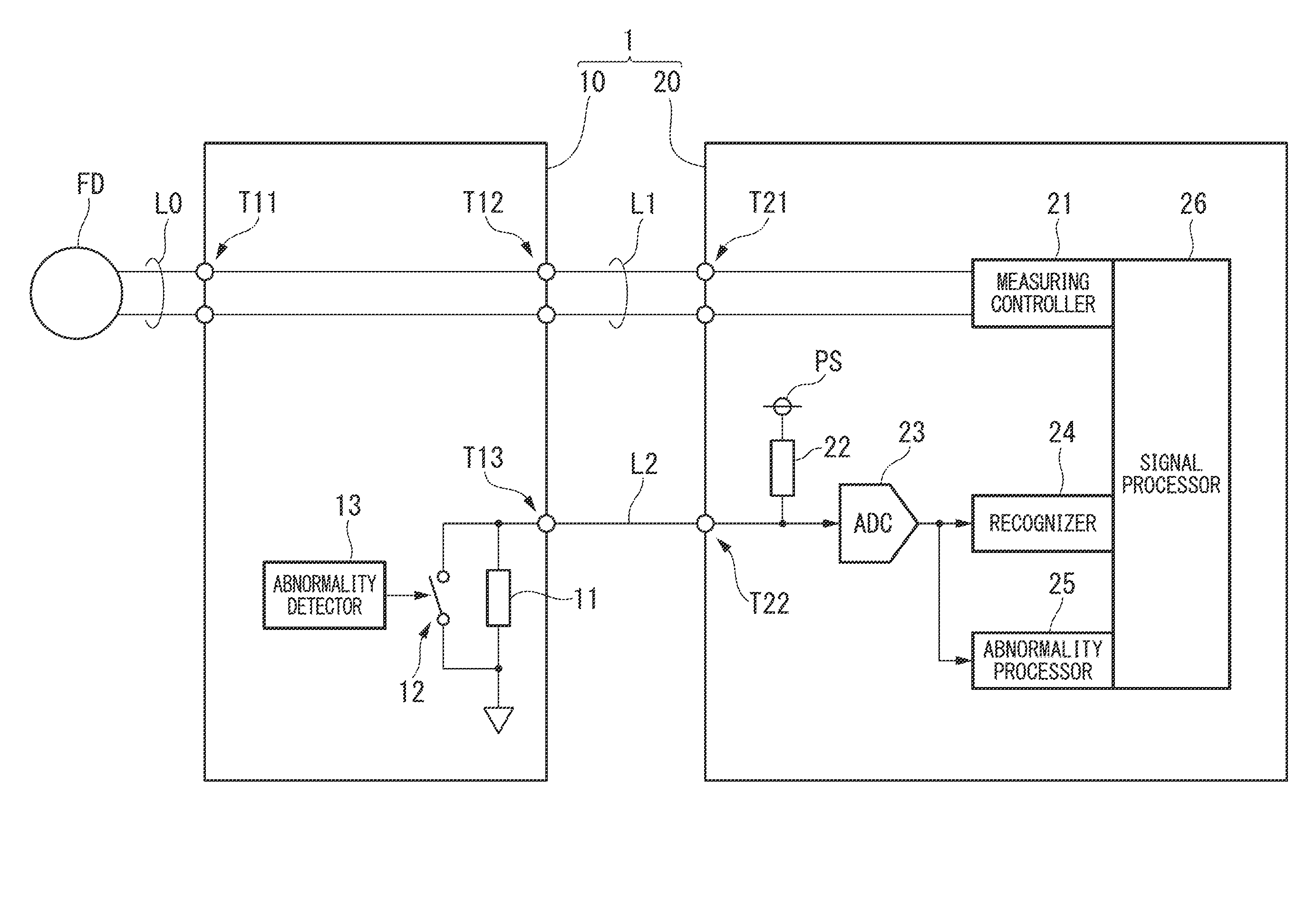
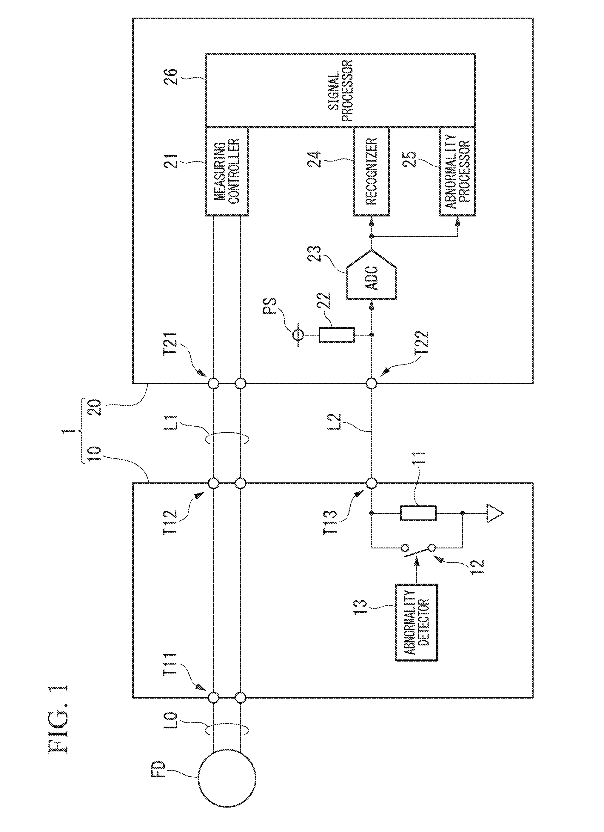
[0049]FIG. 1 is a block diagram showing the main parts of the constitution of a signal processing apparatus according to a first embodiment of the present invention. As shown in FIG. 1, a signal processing apparatus 1 according to the first embodiment includes an interface module 10 and a signal processing module 20, is in connection with a field device FD (device), and performs pre-determined processing for signals transmitted to and received from the field device FD. A plurality of field devices FD and interface modules 10 may be provided with respect to the signal processing module 20. In order to simplify the drawing, one field device FD and one interface module 10 are shown in FIG. 1.

[0050]The field device FD is installed on site, for example, a plant or a factory, and performs at least one of measuring of a measuring target and operating of an operation target required for the control of an industrial process. Specifically, the field device FD includes, for example, a sensor d...

second embodiment

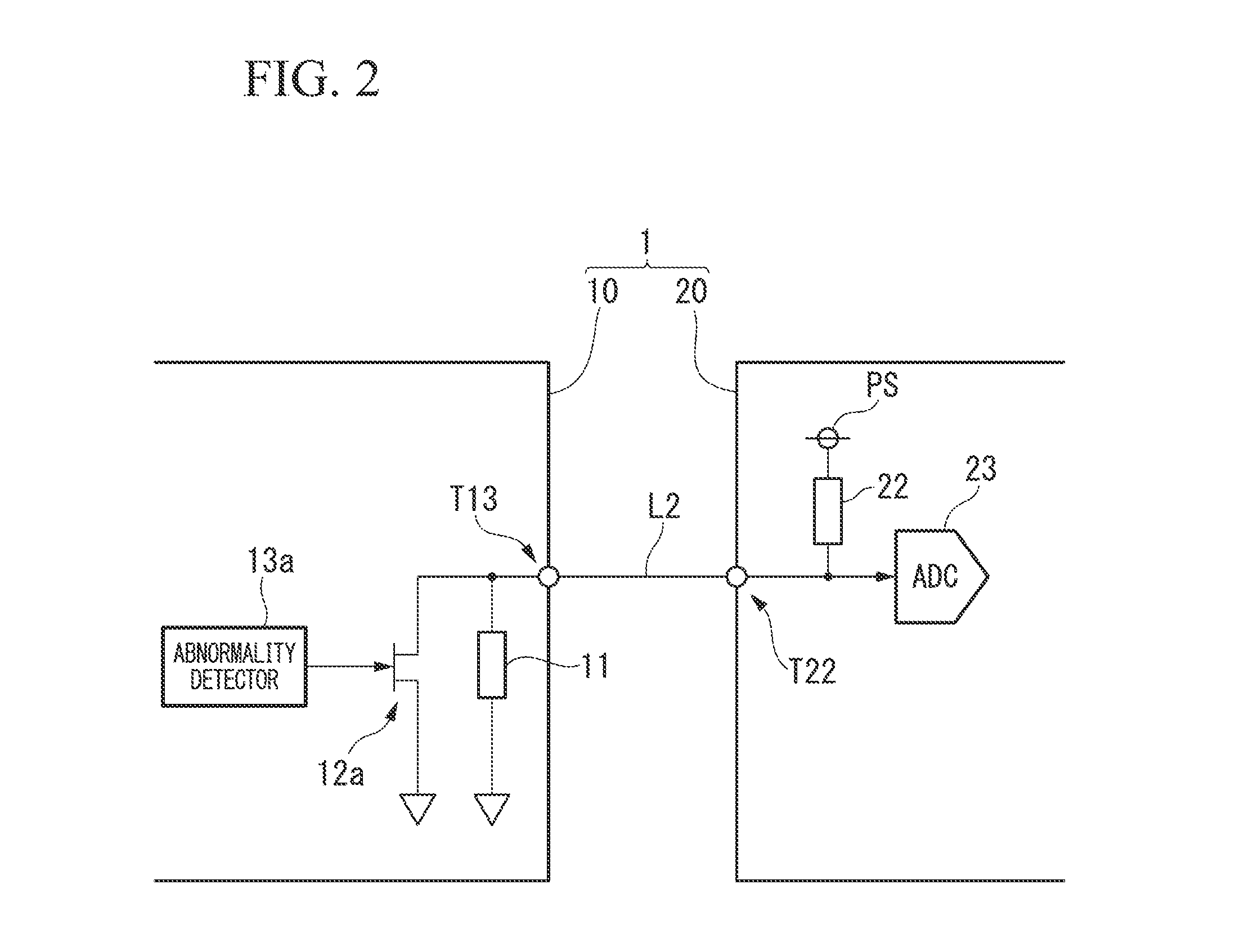
[0075]FIGS. 3A and 3B are block diagrams showing the main parts of the constitution of a signal processing apparatus according to a second embodiment of the present invention. As with the case of FIG. 2, the minimum constitution required for the recognition of the type of an interface module 10 and the notification of the abnormality in the interface module 10 is shown in FIGS. 3A and 3B, and blocks that are similar to those in FIG. 1 are assigned the same reference numerals. The same applies to subsequent drawings.

[0076]As shown in FIGS. 3A and 3B, in a signal processing apparatus 1 according to the second embodiment, compared to the constitution shown in FIG. 1, a circuit (abnormality notification circuit: changer) including a resistance 31 (abnormality notification resistance) and a switch 32 (second switch) is newly provided in the interface module 10, an abnormality detector 33 is provided in the interface module 10 instead of the abnormality detector 13. The signal processing ...

third embodiment

[0084]FIG. 4 is a block diagram showing the main parts of the constitution of a signal processing apparatus according to a third embodiment of the present invention. As shown in FIG. 4, instead of the switch 12 and the abnormality detector 13 shown in FIG. 1, an oscillator 41 and a capacitor 42, and an abnormality detector 43 are provided in a signal processing apparatus 1 according to the third embodiment. The signal processing apparatus 1 having such constitution notifies an abnormality in an interface module 10 by a radio-frequency signal.

[0085]One end of the oscillator 41 is in connection with one end of a resistance 11 via the capacitor 42 (alternating current coupling), and the other end of the oscillator 41 is in connection with ground. The oscillator 41 outputs a square wave or a sine wave radio-frequency signal under the control of the abnormality detector 43. The capacitor 42 alternating-current couples the oscillator 41 to the resistance 11. In particular, the capacitor 4...


PUM


Abstract

A signal processing apparatus includes an interface module and a signal processing module. The interface module includes an identification resistance for identifying the interface module, the interface module being connectable to a device configured to perform at least one of measuring of a measuring target and operating of an operation target. The signal processing module includes a first connection terminal connected to one end of the identification resistance, a first power source connected to the identification resistance via the first connection terminal, a detector configured to detect any one of voltage and electrical current at the first connection terminal, and a signal processor configured to process signals received from and transmitted to the device.

Description

BACKGROUND OF THE INVENTION[0001]1. Field of the Invention[0002]The present invention relates to a signal processing apparatus. Priority is claimed on Japanese Patent Application No. 2013-223891, filed Oct. 29, 2013, the contents of which are incorporated herein by reference.[0003]2. Description of Related Art[0004]A process control system provided in a plant or a factory or the like generally includes on-site devices called field devices (measuring devices, and actuators), a controller controlling the field devices, and a host device managing or controlling the field devices and the controller. The field devices, the controller, and the host device are in connection with one another via a communication means. In such a process control system, the collector is for collecting process values (for example, measured values of the pressure, the temperature, and the flow rate) obtained by the field devices, and controlling the field devices based on the collected process values under the ...

Claims


Application Information

Patent Timeline
IPC IPC(8): G05B9/02G01R31/28G01R19/00H05B44/00
CPCG05B9/02G01R31/2829G01R19/0092G01R19/0084G01D21/00G05B2219/21127G05B19/0423
Inventor JIMI, HIROYUKIHAYASHI, SHUNSUKEWATANABE, IKUTOMO
Owner YOKOGAWA ELECTRIC CORP
Why Eureka
Try Eureka