Magnetic Resonance Facility with a Display Apparatus

Inactive Publication Date: 2015-10-22
SIEMENS AG
View PDF11 Cites 2 Cited by
  • Summary
  • Abstract
  • Description
  • Claims
  • Application Information

AI Technical Summary

Benefits of technology

[0020]A high-frequency coil arrangement may be provided to enclose the patient accommodation region, e.g., following a gradient coil arrangement in an inward direction, with the display apparatus integrated therein or fastened thereto. An integrated embodiment may be provided. For example, the display apparatus may be implemented as part of a support tube of the high-frequency coil arrangement and/or may be fastened to the support tube. While the display apparatus may also be positioned on the cladding of the patient accommodation, which may reduce the space available for the patient, in one embodiment the display apparatus is configured in an integrated manner with the high-frequency coil arrangeme

Problems solved by technology

Because magnetic resonance measurements, in other words magnetic resonance image recordings, frequently also take a long time, the restricted patient accommodation region, which may have a diameter of 60 or 70 cm for example, may be problematic.
Patients frequently find the patient accommodation region restricting and therefore unpleasant, which may result in discomfort on the part of the patient and spontaneous movement/blurred magnetic resonance recordings.
Patients with a tendency to claustrophobia are more badly affected by the restricting nature of the patient accommodation region and they may even refuse to be examined using the magnetic re

Method used


Image

  • Magnetic Resonance Facility with a Display Apparatus
  • Magnetic Resonance Facility with a Display Apparatus
  • Magnetic Resonance Facility with a Display Apparatus

Examples


Embodiment Construction

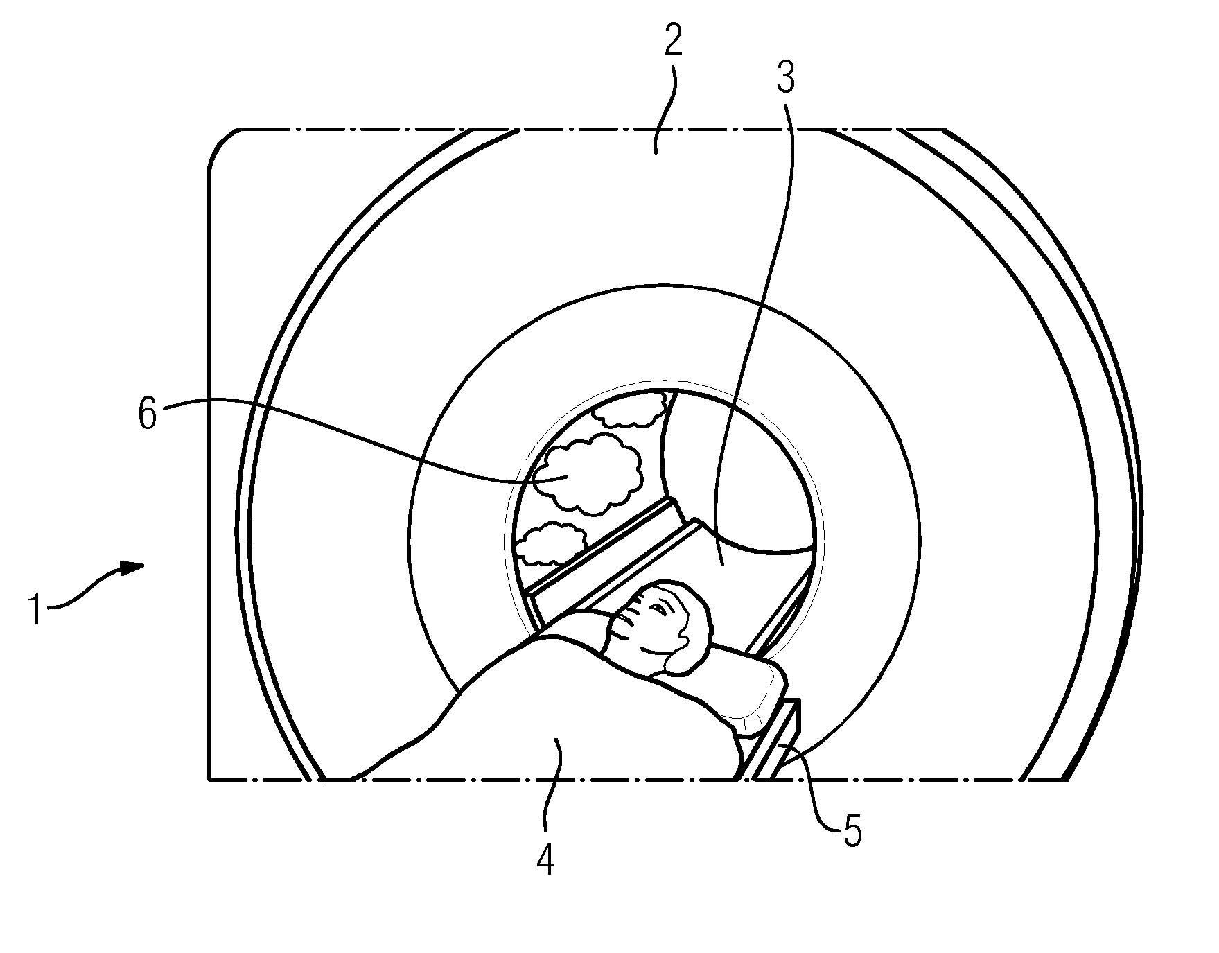
[0029]FIG. 1 shows a simplified view of an inventive magnetic resonance facility 1. The facility 1 includes a main magnet unit 2, which defines a cylindrical patient accommodation region 3, into which a patient 4 may be moved via a patient couch 5 for the magnetic resonance measurement. It may be seen that part of the internal surface of the patient accommodation region 3 is taken up by a display surface 6 of a display apparatus, on which animated clouds are shown as an image, conveying an impression of spatial depth for a patient 4 and also having a calming effect.

[0030]The display apparatus may be implemented on different small display units, which are arranged in the manner of a matrix in rows, each arranged at an angle to one another.

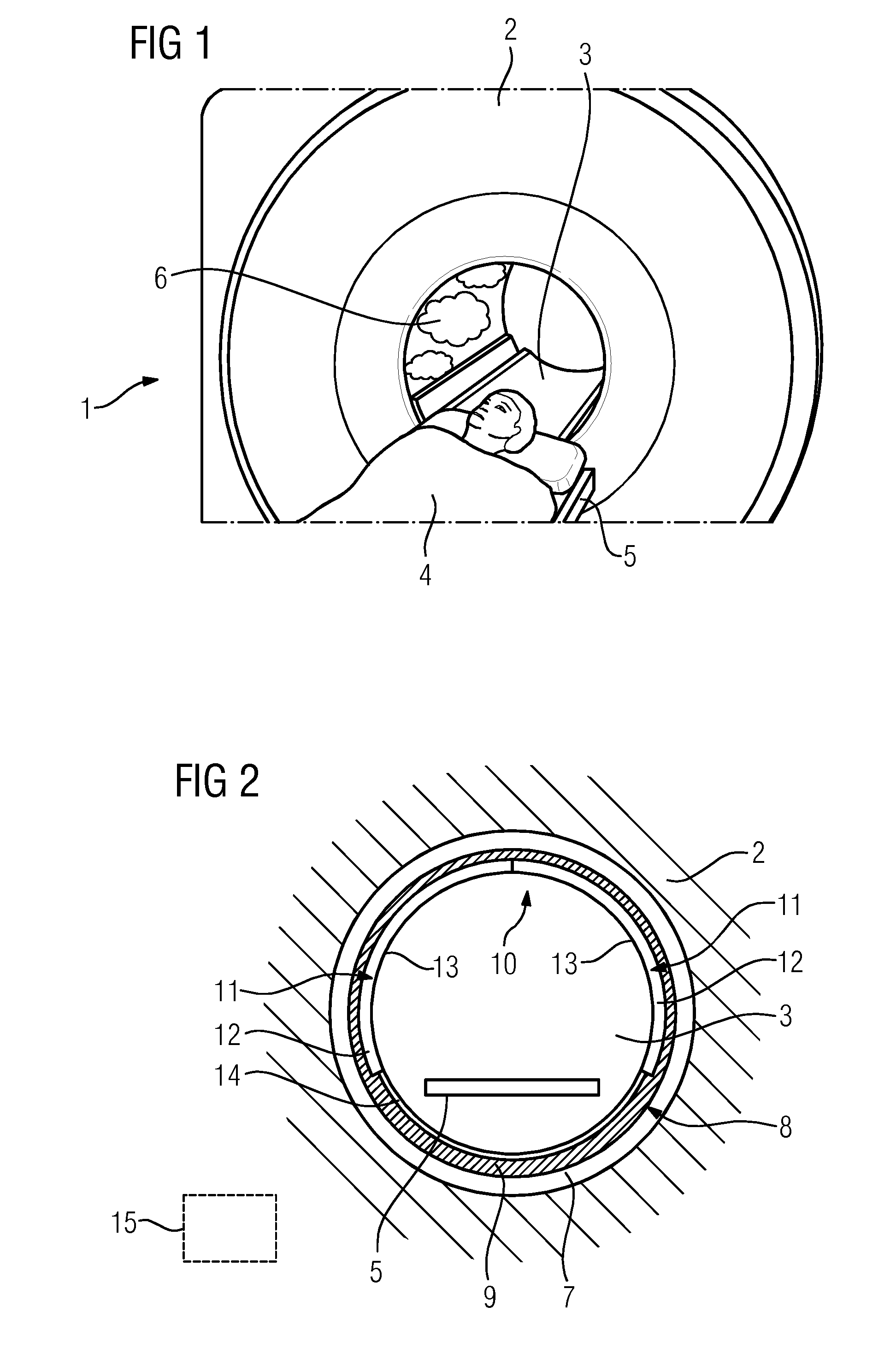
[0031]FIG. 2 shows an embodiment based on a section through the main magnet unit 2 in the region of the patient accommodation region 3. Provided to enclose the patient accommodation region are a gradient coil arrangement 7 (not shown in detail) and,...


PUM


Abstract

A magnetic resonance facility has a main magnet unit with a cylindrical patient accommodation region, and an optical display apparatus with at least one display unit disposed within the patient accommodation region in a region viewable by a patient positioned therein for the magnetic resonance measurement. The display apparatus is shaped at least partially to follow the boundary of the patient accommodation region.

Description

[0001]This application claims the benefit of DE 102014207295.6, filed on Apr. 16, 2014, which is hereby incorporated by reference in its entirety.FIELD[0002]The disclosed embodiments relate to a magnetic resonance facility having a main magnet unit with a cylindrical patient accommodation region.BACKGROUND[0003]Magnetic resonance imaging is well known in the medical field and is now a widely used imaging method. In order to be able to generate powerful and homogeneous magnetic fields, magnetic resonance facilities frequently have a structure, in which a cylindrical patient accommodation region is provided in a main magnet unit, into which the patient may be moved via a patient couch. Because the gradient coil arrangement and a high-frequency coil arrangement are also arranged to enclose the patient accommodation region, the patient accommodation regions, often also referred to as bores or tunnels, have a very small diameter, within which a powerful magnetic field is present, the hom...

Claims


Application Information

Patent Timeline
IPC IPC(8): A61B5/00A61B5/055
CPCA61B5/055A61B5/7445
Inventor BIBER, STEPHANCAMPAGNA, SWENNUFER, STEPHANSPECKNER, THORSTENTHONE, JENS
Owner SIEMENS AG
Why Eureka
Try Eureka