Vehicle control system

Active Publication Date: 2015-11-19
TOYOTA JIDOSHA KK
View PDF4 Cites 4 Cited by
  • Summary
  • Abstract
  • Description
  • Claims
  • Application Information

AI Technical Summary

Benefits of technology

[0014]Thus, the actual turning condition of the vehicle is adjusted to the intended turning condition to improve the turning performance by dif

Problems solved by technology

If the driving force is increased while applying the braking force to the wheels under t

Method used


Image

  • Vehicle control system
  • Vehicle control system
  • Vehicle control system

Examples


Embodiment Construction

)

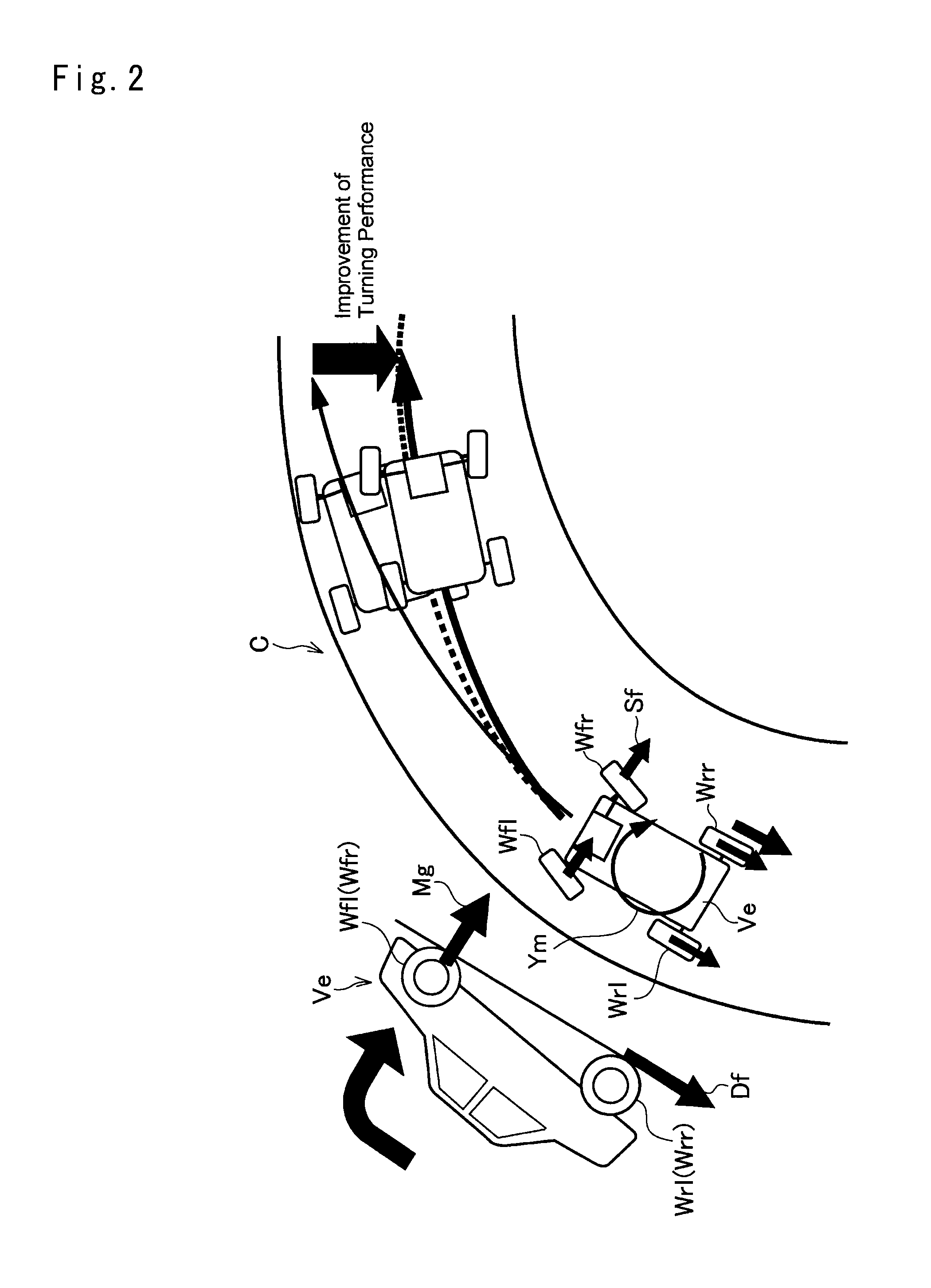
[0019]A preferred example of the present invention will now be described with reference to the accompanying drawings. The vehicle control system of the present invention is configured to control a driving force (or a braking force) applied to wheels in a manner such that an actual turning condition is adjusted to an intended turning condition. Referring now to FIG. 2, there is schematically shown a relation between the driving force applied to drive wheels and the turning condition of a vehicle Ve. The vehicle Ve is comprised of a pair of right and left rear wheels Wrr and Wrl as drive wheels, and a pair of right and left front wheels Wfr and Wfl as steered wheels. In the situation illustrated in FIG. 2, the vehicle Ve is turning a corner C while turning the front wheels Wfr and Wfl. In this situation, a vertical load Mg acting on each front wheel Wfr and Wfl will be varied in response to a change in a driving force Df applied to the rear wheels Wrr or Wrl. Consequently, a lateral ...


PUM


Abstract

A vehicle control system is provided with a first driving force control means that controls a turning performance of a vehicle by controlling a driving force delivered from a prime mover to driving wheels so as to adjust the turning condition of the vehicle to an intended turning condition. The first driving force control means is configured to calculate a correction amount of the driving force required to adjust an actual turning condition of the vehicle to the intended turning condition, and to restrict the correction amount to zero or smaller so as not to increase the driving force if the correction amount is positive value.

Description

TECHNICAL FIELD[0001]The present invention relates to a vehicle control system configured to stabilize turning behavior of a vehicle by controlling a driving force and a braking force of the vehicle.BACKGROUND ART[0002]Control systems for stabilizing a turning condition of a vehicle are known in the art. The conventional control systems are configured to adjust a turning condition exemplified by a yaw rate to a target turning condition determined based on a vehicle speed and a steering angle by controlling a driving force (or a braking force) of the vehicle. Given that a driving force rotating rear wheels is reduced during turning by reducing an engine power or increasing a braking force applied to the rear wheels, a load applied to front wheels being steered is increased and hence a lateral force acting on the front wheels is increased thereby increasing a yaw of the vehicle. To the contrary, given that the driving force rotating the rear wheels is increased, the yaw is reduced. Sp...

Claims


Application Information

Patent Timeline
IPC IPC(8): B60W30/045B60T7/12
CPCB60W30/045B60W2710/12B60T7/12B60T8/1755B60T2270/303B60T2201/16
Inventor OKUMURA, KAZUYAYOSHIKAWA, HAYATO
Owner TOYOTA JIDOSHA KK
Why Eureka
Try Eureka