LED lighting device

a technology of light-emitting diodes and lighting devices, which is applied in the direction of electric lighting sources, electroluminescent light sources, and use of semiconductor lamps. it can solve the problems of generating significant heat at the switching circuit, causing excessive heat generation, and affecting the efficiency of the lighting circuit, so as to reduce the power consumption of the switching unit and prevent excessive heat generation. , the effect of increasing efficiency

Active Publication Date: 2016-01-07
LUMENS
View PDF3 Cites 40 Cited by
  • Summary
  • Abstract
  • Description
  • Claims
  • Application Information

AI Technical Summary

Benefits of technology

[0033]According to some embodiment of the present invention, the LED lighting device includes a resistor end distributing heat of the switch unit so as to prevent the excessive heat generation at the switch unit, when a voltage equal to or greater than the rated voltage is inputted. Therefore, the LED lighting device provides an effect of maintaining the normal operation of the switch unit formed of IC.
[0034]In addition, according to some embodiment of the present invention, since the forward voltage of the LED channel is redistributed, the LED lighting device provides effects of decrease in the power consumption at the switch unit and efficiency increase.
[0035]In addition, according to some embodiment of the present invention, the LED lighting device provides an effect that the dimming control is performed by controlling the operation number of the LED or the operation current of the LED by using the variable resistor.
[0036]In addition, according to some embodiment of the present invention, the LED lighting device provides an effect of providing a constant brightness by the reduction of a flicker phenomenon caused by the input voltage.
[0037]In addition, according to some embodiment of the present invention, the LED lighting device provides an effect of the protection of the switch unit by blocking an over-current flowing through the switch unit.

Problems solved by technology

Since the conventional switching circuit includes the voltage sensing circuit or the period sensing circuit, its entire size is too big.
In addition, the switching circuit is formed by a FET, and the FET IC is a sensitive component, and very weak to heat.
Herein, when an input voltage equal to or greater than a rated voltage is inputted, a significant amount of heat may generate at the switching circuit.
That is, when the input voltage equal to or equal to or greater than the rated voltage is inputted, current with high amperes flows through the switching circuit, thereby generating a significant amount of heat at the switching circuit.
However, since a voltage sensing circuit sensing the input voltage is included in U.S. Pat. No. 6,989,807, an area for mounting more LEDs decreases, and a significant amount of heat generates at the switching circuit when a voltage equal to or greater than the rated voltage is inputted, thereby increasing power consumption, reducing its efficiency, and increasing occurrence of malfunctions of the circuit due to the significant amount of heat generated at the switching circuit.

Method used


Image

  • LED lighting device
  • LED lighting device
  • LED lighting device

Examples


Embodiment Construction

Technical Problem

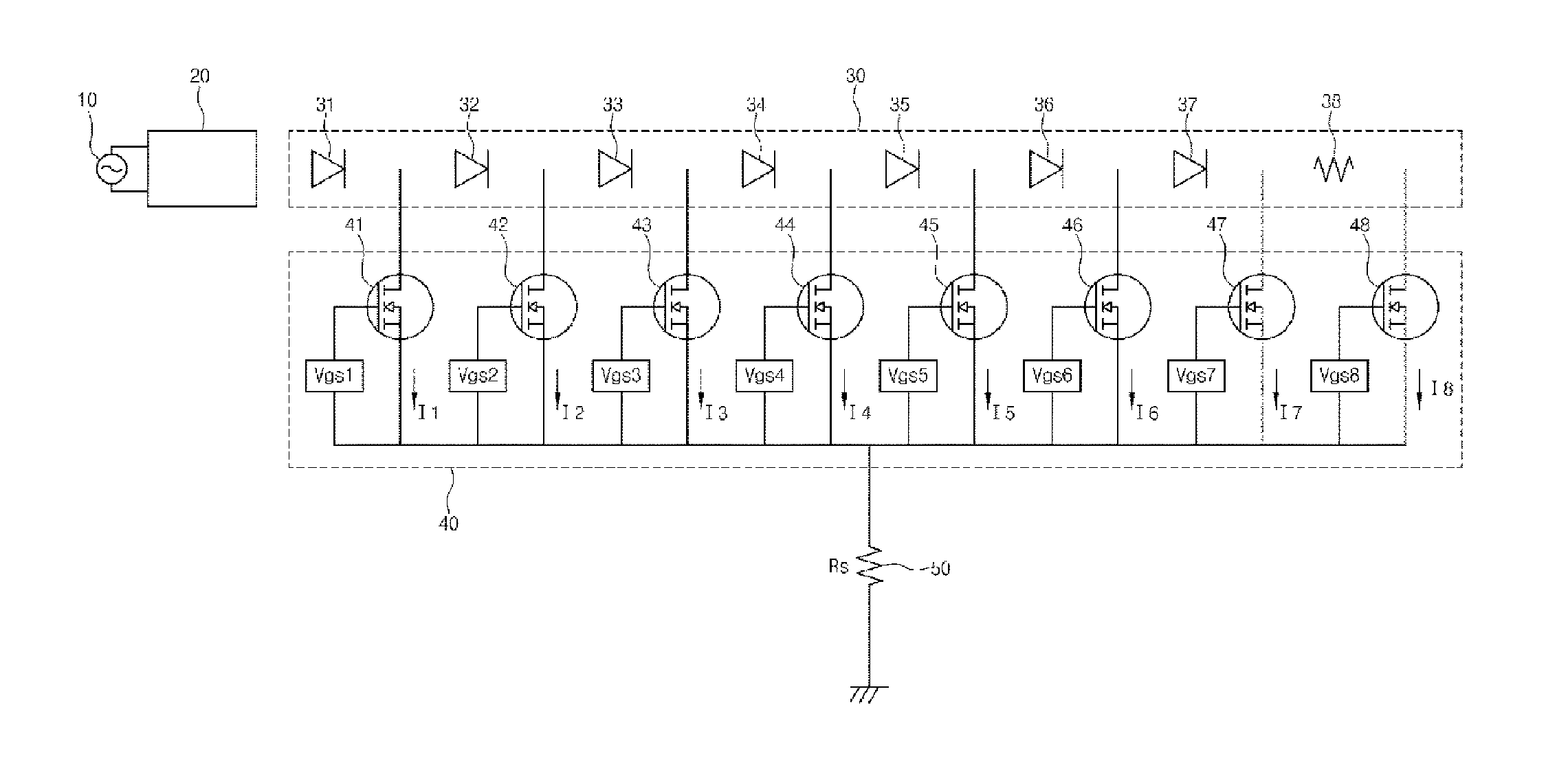
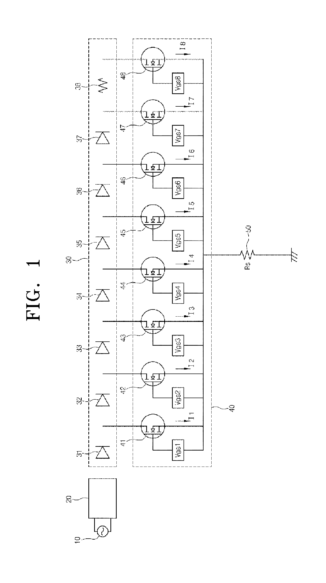
[0007]The present invention has an objective to decrease the heat generation at a switch unit and protect the switch unit by generating heat at a resistor to distribute the heat generation when a voltage equal to or greater than the rated voltage is inputted to an LED unit in which a plurality of LEDs are connected.

[0008]The present invention has an objective to form a switch unit without any input voltage sensing circuit or any input period sensing circuit sensing an input voltage, thereby adding additional LEDs can be added in a restricted area.

[0009]The present invention has an objective to prevent a flicker phenomenon by connecting a capacitor to an LED.

[0010]The present invention has an objective to economically control dimming of LEDs.

[0011]Other objectives of the present invention can be easily understood by the description of following embodiments.

Technical Solution

[0012]According to an aspect of the present invention, an LED lighting device, including: a po...


PUM


Abstract

An LED lighting device comprises: a rectification circuit unit for receiving input power from a power source unit and outputting a rectified power; an LED unit having a plurality of LED channels connected in series and a resistor unit connected to the last end of the LED channels; a current sensing resistor; and a switch circuit unit comprising a plurality of switches, wherein an nth switch is connected to the rear end of an nth LED channel so as to control an operation of the nth LED channel and is controlled by a sum of a current of the nth switch and a current of an (n+1)th switch, which flows through the current sensing resistor.

Description

TECHNICAL FIELD[0001]The present invention is related to an LED (Light Emitting Diode) lighting device. In particular, the present invention is related to an LED lighting device in which a switch operating an LED is automatically converted by an input voltage and the heat generation on a switching IC, when a voltage equal to or greater than a rated voltage is inputted, can be prevented.BACKGROUND ART[0002]An LED diode (hereinafter, it is referred to “LED”) is used in lighting devices to satisfy requirements of low power consumption, high efficiency, and long lifetime.[0003]In order to use an LED as a light source, a switching circuit to operate the LED according to an input voltage is necessary.[0004]A conventional switching circuit includes a voltage sensing circuit or period sensing circuit to sense the amount of a voltage or an input period of a voltage, thereby controlling a switch corresponding to an LED. Since the conventional switching circuit includes the voltage sensing cir...

Claims


Application Information

Patent Timeline
Patent Type & Authority Applications(United States)
IPC IPC(8): H05B44/00
CPCH05B33/0812H05B33/0848H05B45/395H05B45/48H05B45/10Y02B20/30H05B47/105
Inventor GONG, MYEONG-KOOKYOO, KYUNG HOCHOO, KIL HOKIM, JONG ILLEE, YOUNG JUNEHAN, SEUNG JONG
Owner LUMENS
Why Eureka
Try Eureka