Aircraft wing for receiving a plurality of different wing tip devices

Inactive Publication Date: 2016-05-12
AIRBUS OPERATIONS LTD
View PDF2 Cites 0 Cited by
  • Summary
  • Abstract
  • Description
  • Claims
  • Application Information

AI Technical Summary

Benefits of technology

The present invention provides a wing that can be used with either of two different wing tip devices, making it easy to modify the functionality of the aircraft without needing to redesign the wing. This allows the operator to use the aircraft in different ways without having to change the design of the wing. Additionally, interchangeable wing tip devices can be used for different mission profiles, further increasing the flexibility and potential re-sale value of the aircraft. The wing is designed to perform well in both configurations, but may not be optimal in either.

Problems solved by technology

Thus, whilst the wingtip fence can still be used on the aircraft wing, that wing is heavier than it would ideally need to be.

Method used


Image

  • Aircraft wing for receiving a plurality of different wing tip devices
  • Aircraft wing for receiving a plurality of different wing tip devices
  • Aircraft wing for receiving a plurality of different wing tip devices

Examples


Embodiment Construction

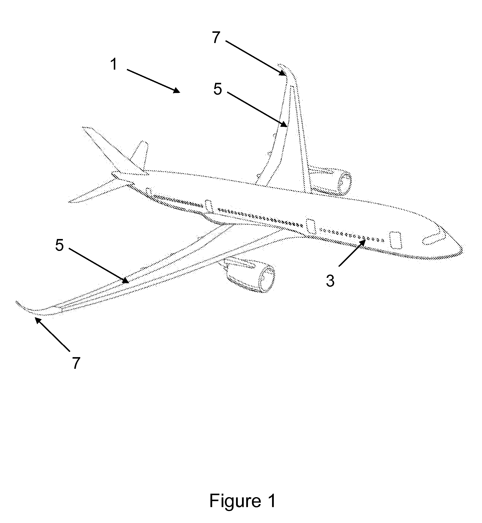
[0031]FIG. 1 shows a passenger aircraft 1 according to a first embodiment of the invention. The aircraft 1 comprises a fuselage 3 and wings 5. Each wing 5 has a winglet 7 mounted at its tip. As is well known in the art, the winglet 7 can improve the aircraft performance, particularly is relation to a reduction in induced drag.

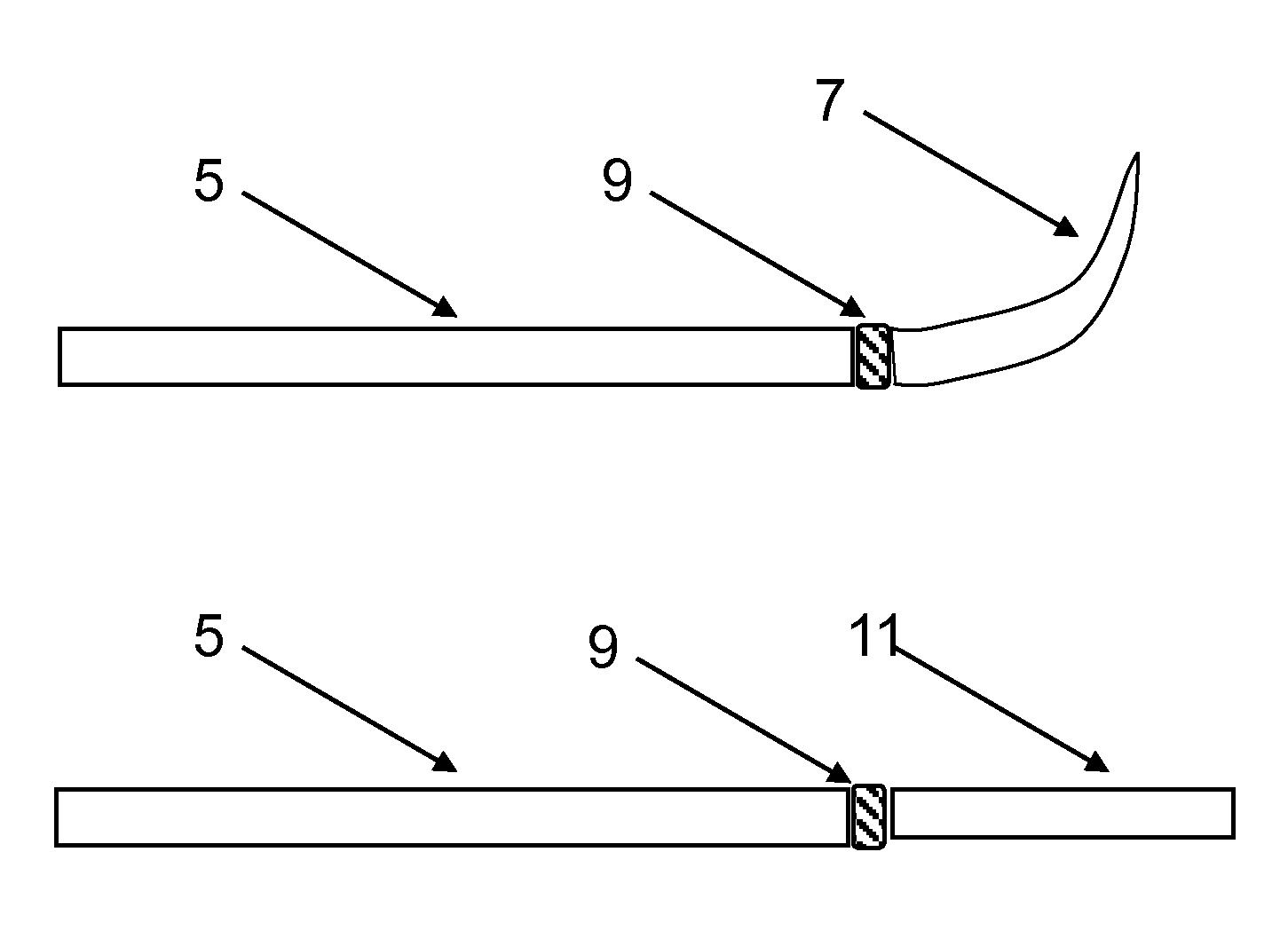
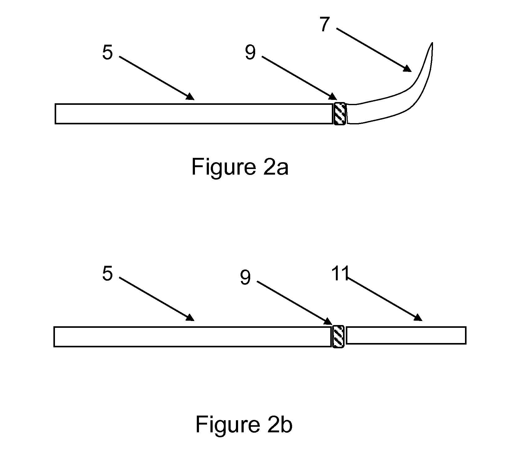
[0032]The winglet 7 attaches to its respective wing 5 at a wing-box-to-wing-tip connection interface 9 (not visible in FIG. 1 but see FIGS. 2a and 2b). In the first embodiment of the invention, the connection interface 9 is arranged to receive two different wing tip devices: the winglet in FIGS. 1 and 2a, and the planar wing tip extension 11 shown in FIG. 2b. By providing a common connection interface 9 arranged to receive the two different wing tip devices 7, 11 it is possible for different wing tip devices 7, 11 to be installed on the wing, depending on what device 7, 11 is most suitable for a particular mission profile. This enables the aircraft 1 to be rela...


PUM


Abstract

An aircraft wing, the wing having a connection interface at the tip of the wing, and the wing being configurable between a first configuration in which a first wing tip device is connected to the connection interface, and a second configuration in which a second wing tip device is connected to the connection interface to replace the first wing tip device. The design of the wing is such that it is designed for performance in both the first and the second configurations.

Description

BACKGROUND OF THE INVENTION[0001]The present invention relates to aircraft wings, and more particularly to aircraft wings for receiving a plurality of different wing tip devices, and to methods of designing such wings and / or wing tip devices.[0002]It is well known to use wing tip devices (such as winglets, tip fences, planar extension etc.) on aircraft wings. Wing tip devices may be retro-fitted to existing wings, or incorporated into a new aircraft wing as part of the initial design process.[0003]When designing a new aircraft wing, the wing tends to be designed specifically for use with a particular wing tip device. Thus the wing is designed for performance with the wing tip device fitted.[0004]When retro-fitting a wing tip device, the wing to which the device is to be fitted has usually been previously designed for performance without a wing tip device, thus some modification of the wing may be required (e.g. structural reinforcement to cope with different structural loading). The...

Claims


Application Information

Patent Timeline
IPC IPC(8): B64C23/06G06Q30/06G06F17/50B64C3/38
CPCB64C23/065B64C3/38G06Q30/0641G06F17/5095B64C2211/00B64C23/069G06F30/15Y02T50/10B64C3/58B64C5/08
Inventor DEE, JONATHANORCHARD, MATTHEW NOEL
Owner AIRBUS OPERATIONS LTD
Why Eureka
Try Eureka