Preloaded surgical instrument interface

Active Publication Date: 2016-06-30
INTUITIVE SURGICAL OPERATIONS INC
View PDF1 Cites 82 Cited by
  • Summary
  • Abstract
  • Description
  • Claims
  • Application Information

AI Technical Summary

Benefits of technology

[0057]The driven disk includes a driven interface. The driven interface includes an engagement receptacle, drive dog receptacles, and a rotation disable element. The rotation disable element

Problems solved by technology

Robotically controlled systems such as employed for minimally invasive medical procedures can include large and complex equipment to precisely control and drive relatively small tools or instruments.
However, the instrument 150 being installed may move in

Method used


Image

  • Preloaded surgical instrument interface
  • Preloaded surgical instrument interface
  • Preloaded surgical instrument interface

Examples


Embodiment Construction

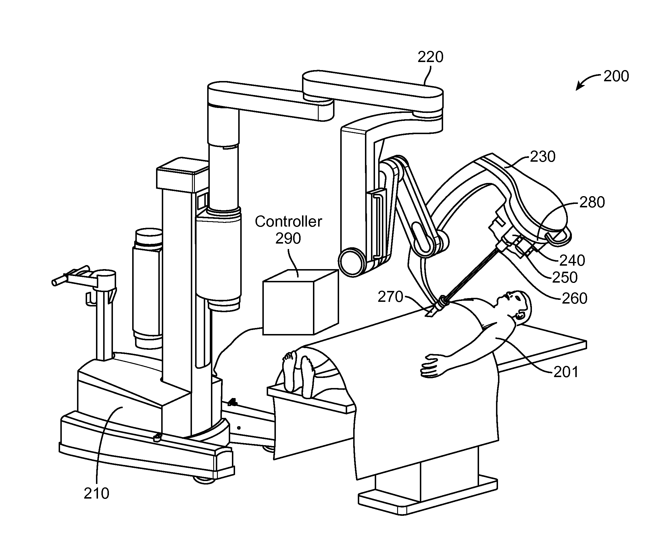
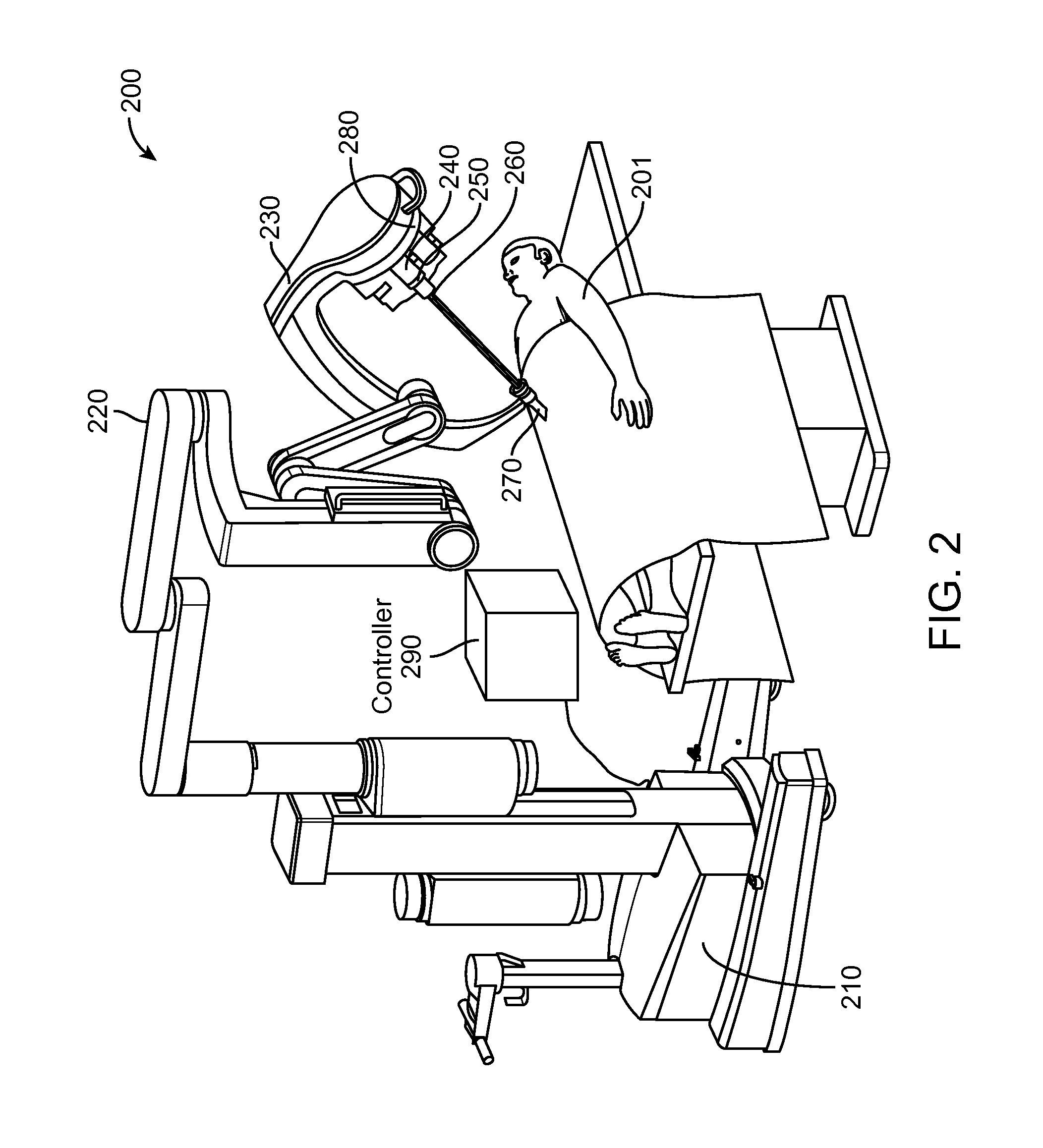
[0112]In one aspect, a surgical system 200 (FIG. 2), e.g., a minimally invasive teleoperated surgical system, includes a patient-side cart 210 having an arm 220. At an end of arm 220 is an entry guide manipulator 230. Mounted on entry guide manipulator 230 is a master instrument manipulator 280 that in turn supports multiple surgical device assemblies. In one aspect, a surgical device assembly includes a surgical instrument manipulator assembly 240, an instrument sterile adapter assembly 250, and a surgical instrument 260.

[0113]Surgical instrument manipulator assembly 240 is sometimes referred to as instrument manipulator assembly 240. Instrument sterile adapter assembly 250 is sometimes referred to as sterile adapter assembly 250.

[0114]Entry guide manipulator 230 changes the pitch and yaw of the surgical device assemblies as group. A main tube of each surgical instrument 260 extends through a different channel in a single port entry guide 270. Single port entry guide 270 is mounted...


PUM


Abstract

A surgical system (200) includes a surgical instrument (260) that is sensitive to backlash that would adversely affect the transmission of controlled torque and position to the surgical instrument. The surgical instrument (260) is coupled to motors in a surgical instrument manipulator assembly (240) via a mechanical interface. The combination of the mechanical interface and surgical instrument manipulator assembly (240) have low backlash, e.g., less than 0.7 degrees. The backlash is controlled in the surgical instrument manipulator assembly (240). From the drive output disk (545) in the surgical instrument manipulator assembly to the driven disk (964) of the surgical instrument, the mechanical interface has zero backlash for torque levels used in surgical procedures.

Description

RELATED APPLICATIONS[0001]This application claims priority to and the benefit of:[0002]U.S. Patent Application No. 61 / 866,115, (filed Aug. 15, 2013, disclosing “PRELOADED SURGICAL INSTRUMENT INTERFACE,” by Thomas G. Cooper et al.);[0003]U.S. Patent Application No. 61 / 866,117, (filed Aug. 15, 2013, disclosing “VARIABLE INSTRUMENT PRELOAD MECHANISM CONTROLLER,” by Todd R. Solomon et al.);[0004]U.S. Patent Application No. 61 / 866,118, (filed Aug. 15, 2013, disclosing “ACTUATOR INTERFACE TO INSTRUMENT STERILE ADAPTER,” by Thomas G. Cooper et al.);[0005]U.S. Patent Application No. 61 / 866,120, (filed Aug. 15, 2013, disclosing “INSTRUMENT STERILE ADAPTER DRIVE FEATURES,” by Thomas G. Cooper et al.);[0006]U.S. Patent Application No. 61 / 866,124, (filed Aug. 15, 2013, disclosing “INSTRUMENT STERILE ADAPTER DRIVE INTERFACE,” by Robert E. Holop et al.); and[0007]U.S. Patent Application No. 61 / 866,125, (filed Aug. 15, 2013, disclosing “ROBOTIC INSTRUMENT DRIVEN ELEMENT,” by Thomas G. Cooper et al...

Claims


Application Information

Patent Timeline
IPC IPC(8): A61B34/30
CPCA61B2034/303A61B34/30A61B2017/00477A61B2034/302F16H25/2003F16H2025/2075F16H25/2015F16D2001/102A61B2017/00367A61B2017/00398A61B34/70
Inventor COOPER, THOMAS G.MCGROGAN, ANTHONY KHOLOP, ROBERT E.SOLOMON, TODD R.DUVAL, EUGENE F.ANDERSON, KENT M.
Owner INTUITIVE SURGICAL OPERATIONS INC
Why Eureka
Try Eureka