Liquid pump

a technology of liquid pump and pump body, which is applied in the direction of liquid fuel engine, positive displacement liquid engine, piston pump, etc., can solve the problems of affecting the operation performance or the durability of the motor arrangement, affecting the accuracy of the shaft, so as to achieve stable performance of the fuel pump and stabilize the pump performance. , the effect of high quality

Active Publication Date: 2016-07-14
AISAN IND CO LTD
View PDF12 Cites 0 Cited by
  • Summary
  • Abstract
  • Description
  • Claims
  • Application Information

AI Technical Summary

Benefits of technology

[0022]The principle of the present disclosure with respect to the liquid pump discussed above is applicable to a fuel pump that pumps fuel (fuel as liquid), which is drawn from a fuel tank. For example, a fuel pump for a vehicle is required to have a high quality to continuously implement a stable performance of the fuel pump. When the fuel pump of the present disclosure is applied, it is possible to ensure the appropriate axis accuracy of the motor arrangement. Thereby, it is possible to stabilize the pump performance that is achieved with the rotatable member, which is rotated by the motor arrangement.

Problems solved by technology

Particularly, when the sink mark and / or the deformation is formed in the tubular portion, which holds the bearing that rotatably supports the one end portion of the shaft, it will cause deviation of the central axis of the shaft or tilt of the central axis of the shaft at the time of installing the shaft.
Thereby, required axis accuracy of the shaft, such as required coaxiality or required perpendicularity of the shaft, cannot be ensured.
As a result, the operational performance or the durability of the motor arrangement may possibly be adversely influenced.

Method used


Image

  • Liquid pump
  • Liquid pump
  • Liquid pump

Examples


Embodiment Construction

[0028]Hereinafter, an embodiment of the present disclosure will be described with reference to the accompanying drawings.

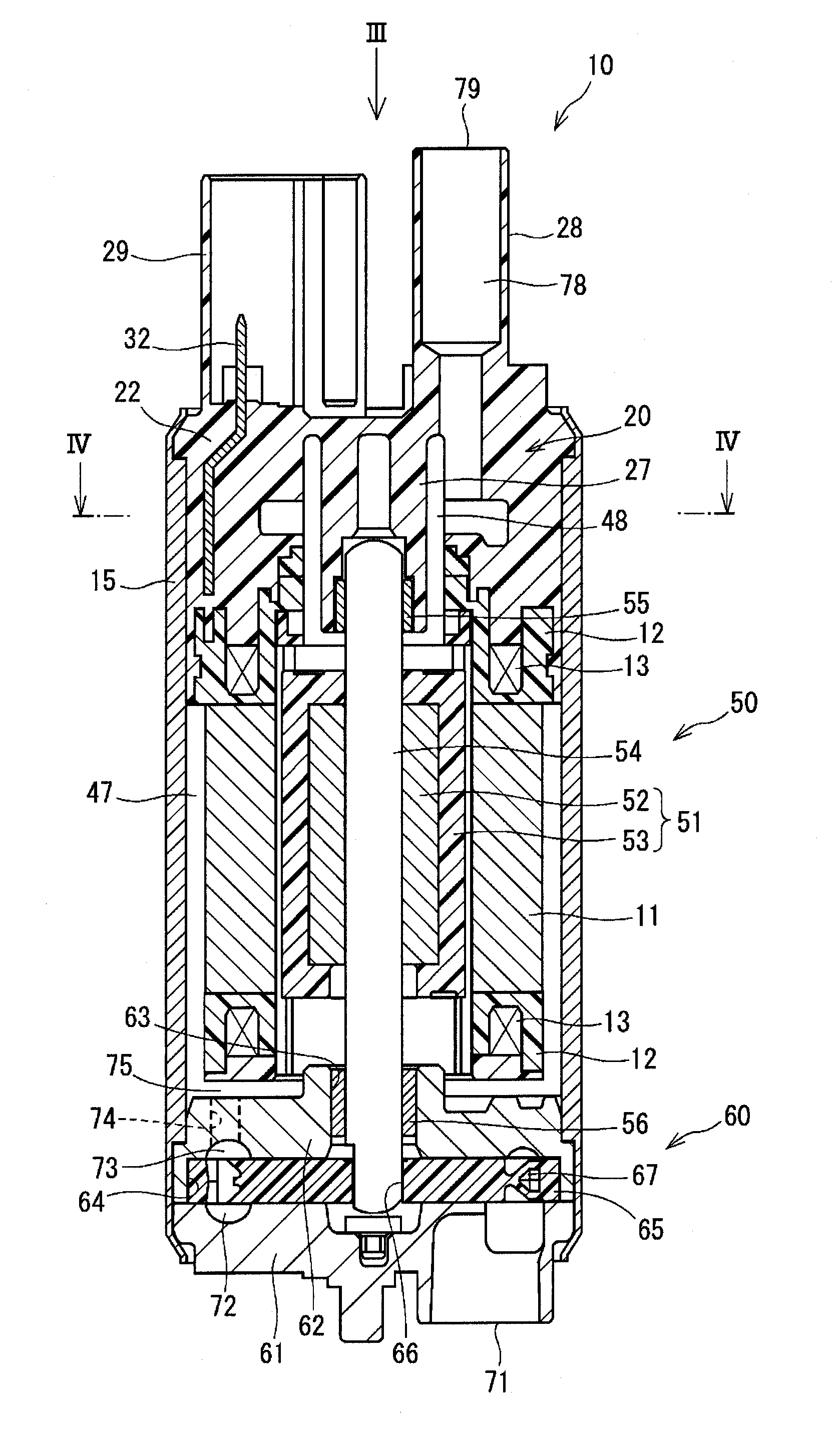
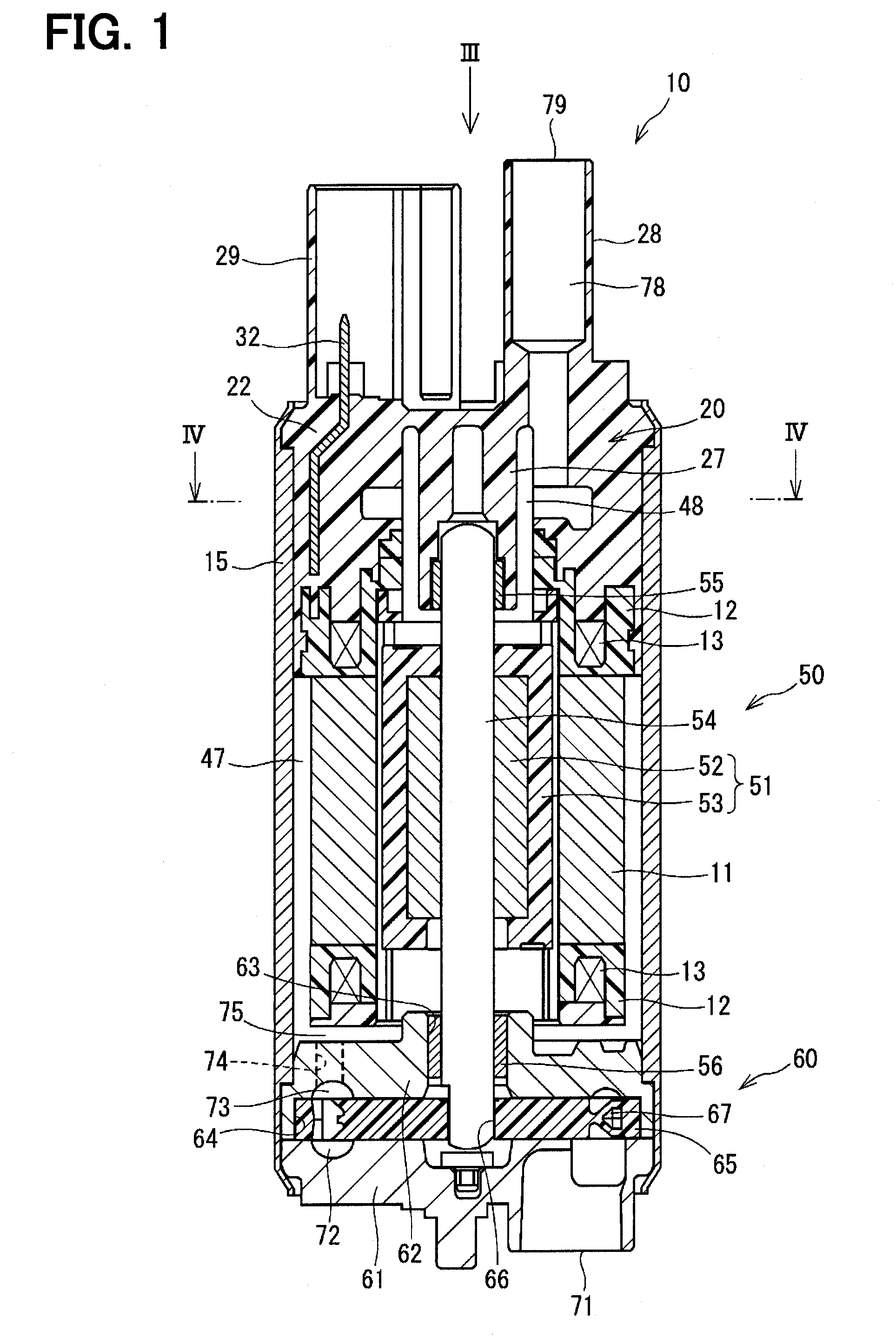
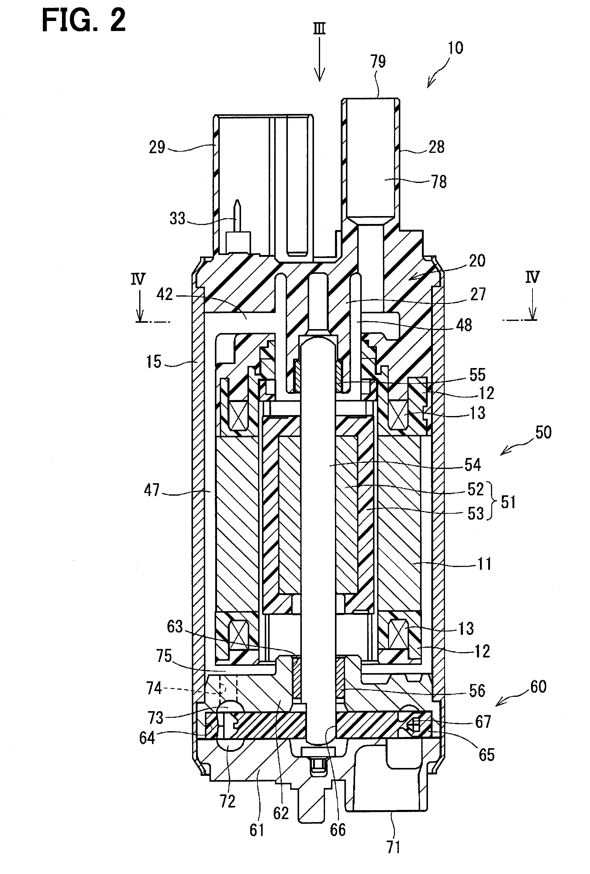
[0029]A fuel pump, which serves as a liquid pump, according to the embodiment of the present disclosure will be described with reference to FIGS. 1 to 4.

[0030]The fuel pump 1 draws fuel of a fuel tank (not shown) through a suction port 71 and discharges the drawn fuel from a discharge port 79, which is an opening of a discharge conduit 28, to an internal combustion engine. The fuel pump 1 includes a motor arrangement 50 and a pump arrangement 60. An outer shell of the fuel pump 1 includes a housing 15, a cover end 20 and a pump cover 61. In the following description of the fuel pump 1, the upper side of FIGS. 1 and 2 will be referred to as a discharge port 79 side, and the lower side of FIGS. 1 and 2 will be referred to as a suction port 71 side.

[0031]The housing 15 is configured into a cylindrical tubular form and is made of metal (e.g., iron).

[0032]The cover end...


PUM


Abstract

A cover end of a fuel pump is formed by resin molding and has a tubular portion, which holds a bearing that is placed along a central axis of the tubular portion and rotatably supports one end portion of a shaft of a motor arrangement. Furthermore, three terminals, which supply three-phase electric power received from an outside to windings on a phase-by-phase basis, are insert molded in the cover end. In the cover end, a first transverse passage, which is formed between the first terminal and the second terminal in a circumferential direction, and a second transverse passage, which is formed between the second terminal and the third terminal in the circumferential direction, are configured into a form of V-shape, which diverges in a radially outer direction, in a view taken in an axial direction.

Description

CROSS REFERENCE TO RELATED APPLICATION[0001]This application is based on and incorporates herein by reference Japanese Patent Application No. 2013-191594 filed on Sep. 17, 2013.TECHNICAL FIELD[0002]The present disclosure relates to a liquid pump.BACKGROUND ART[0003]Previously, a liquid pump, which rotates a rotatable member, such an impeller, by a motor arrangement received in an inside of the liquid pump to pump liquid, is known. In general, in the liquid pump having the above-described motor arrangement, the liquid, which is drawn through a suction port formed at one axial end of the liquid pump, is pressurized and is discharged to an outside through a discharge port formed at the other axial end of the liquid pump.[0004]A discharge conduit, which forms the discharge port, is formed integrally with a cover end made of resin in such a manner that the discharge conduit projects from the axial end portion of the liquid pump. A tubular portion, which holds a bearing that rotatably sup...

Claims


Application Information

Patent Timeline
Patent Type & Authority Applications(United States)
IPC IPC(8): F02M37/08F04D29/18F04D29/52F04D3/00F04D13/06
CPCF02M37/08F04D3/005F04D29/181F04D29/528F04D13/06H02K5/22F02M37/10F02M2037/082F04D5/002F04D13/0693
Inventor NAGATA, KIYOSHIHAYAKAWA, TETSUOOOTAKE, MASAYA
Owner AISAN IND CO LTD
Why Eureka
Try Eureka