Rotation Device and Power Supply System

a technology of rotating devices and power supply systems, applied in the direction of gearing details, machines/engines, gearing, etc., can solve the problem of extremely low friction loss, and achieve the effect of effective utilization of electrical power

Active Publication Date: 2016-09-15
SIMPLE TOKYO
View PDF6 Cites 2 Cited by
  • Summary
  • Abstract
  • Description
  • Claims
  • Application Information

AI Technical Summary

Benefits of technology

[0018]Thus, according to the present invention, it is possible to maintain electrical power energy of nighttime power as a rotational energy of the rotation device, and also to maintain the electrical power energy of the nighttime power as ele

Problems solved by technology

At the time the center of gravity of the at least one weight member rises, since the at least one ro

Method used


Image

  • Rotation Device and Power Supply System
  • Rotation Device and Power Supply System
  • Rotation Device and Power Supply System

Examples


Embodiment Construction

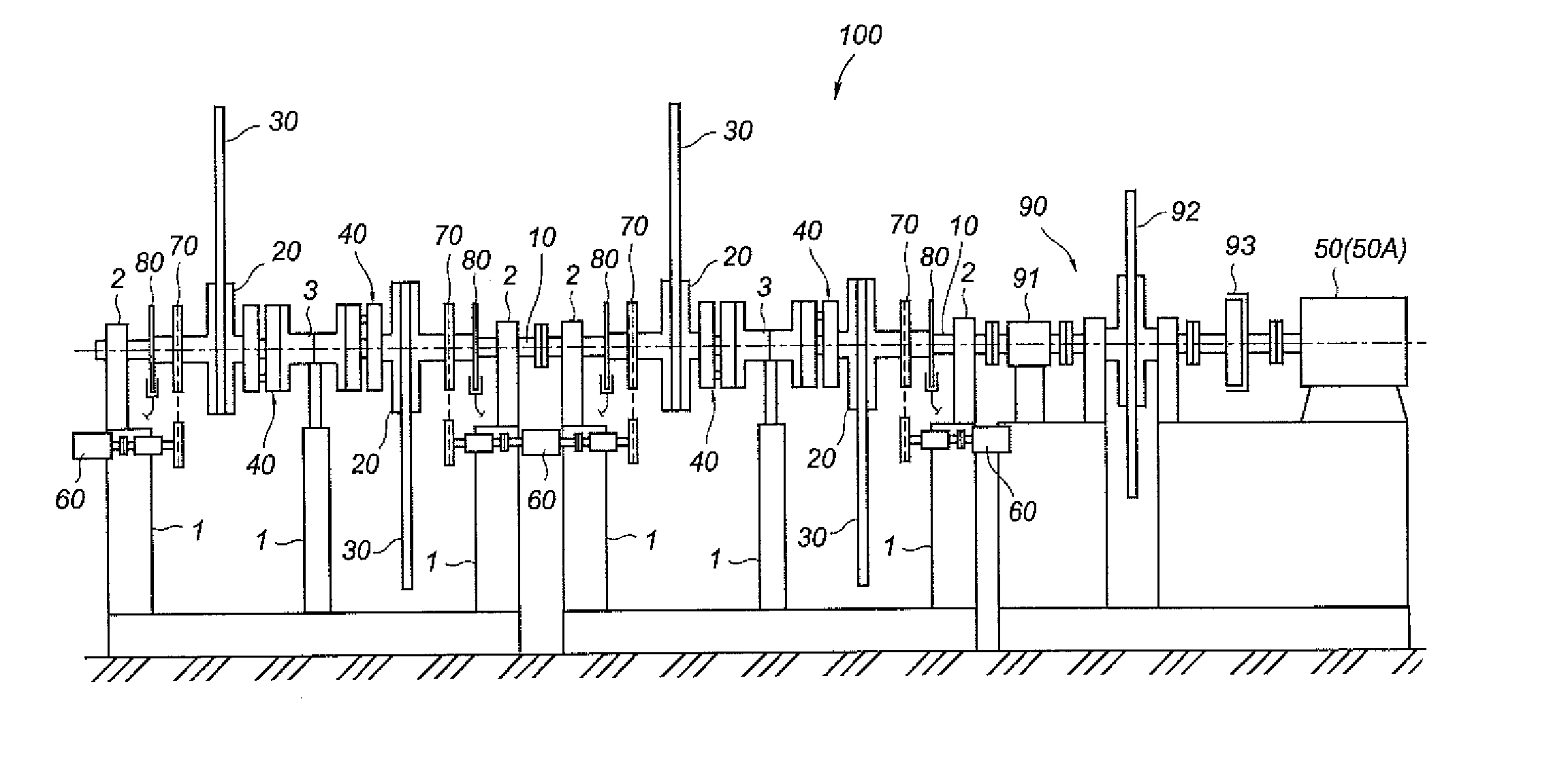
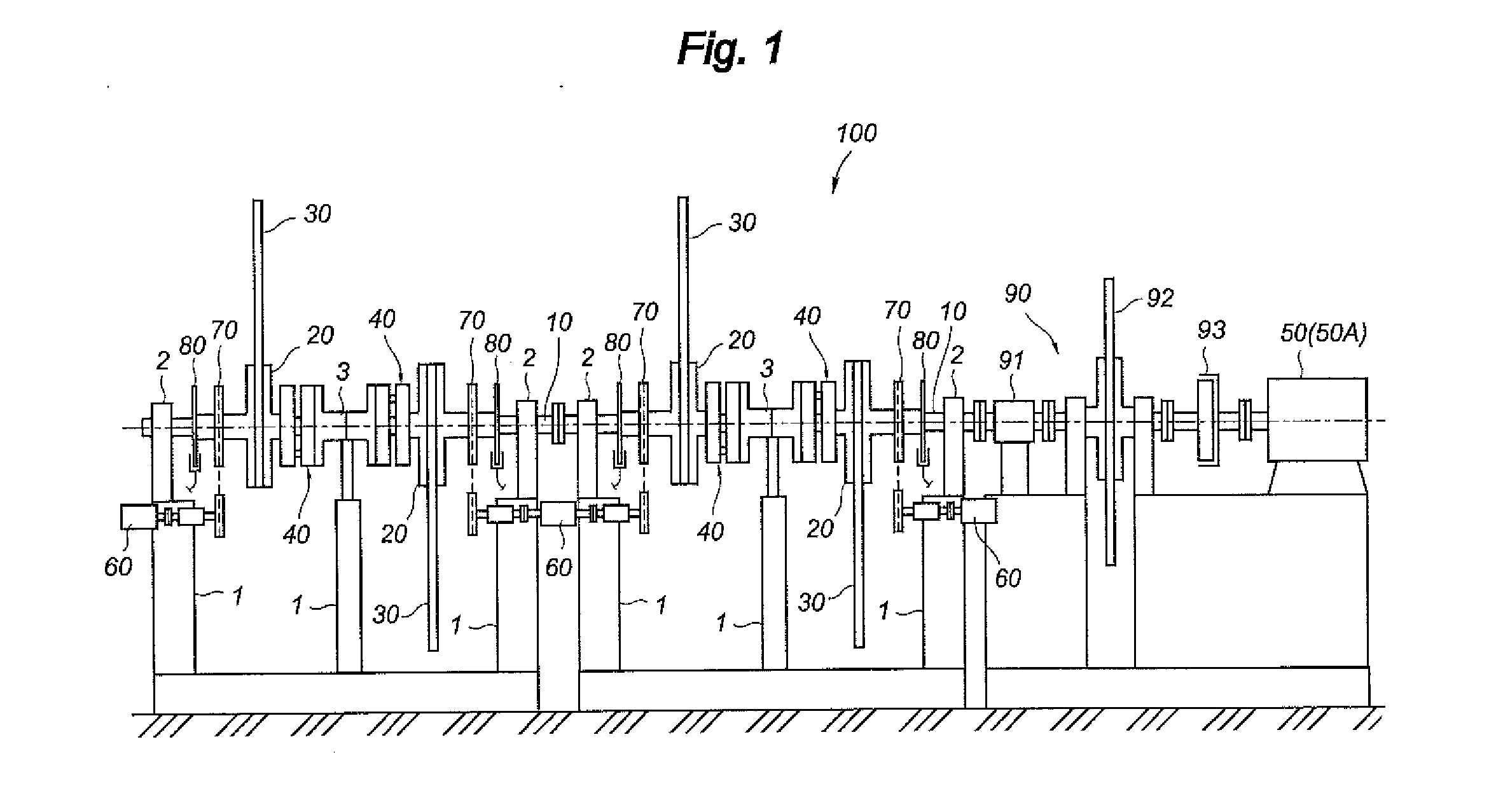
[0030]Hereinafter, a preferred embodiment of a rotation device according to the present invention will be described. FIGS. 1, 23a and 3b, 4, 5a and 5b, 6a to 6d, 7a to 7d, 8a to 8d and 9a to 9d schematically illustrate a configuration of the embodiment of the rotation device according to the present invention.

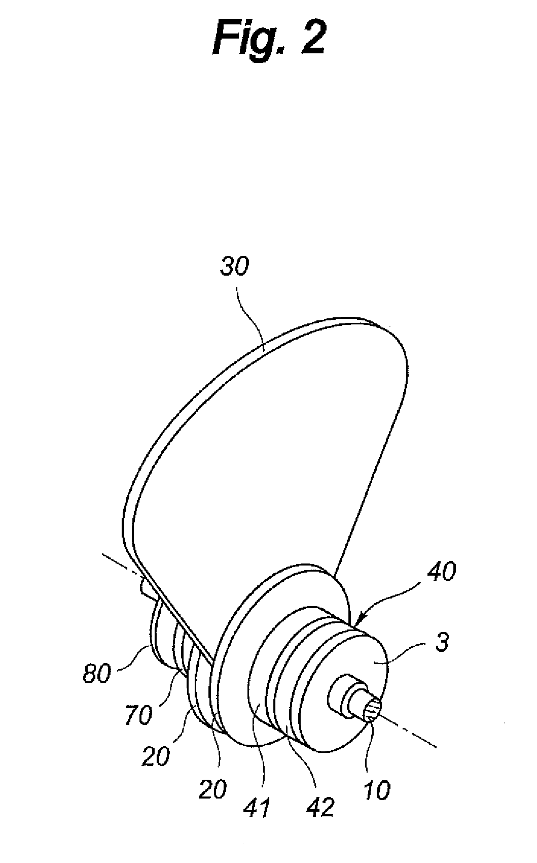
[0031]FIG. 1 shows the configuration of the rotation device 100 having four sets of rotary plate members 20, weight members 30 and clutch mechanisms 40, and FIG. 2 shows an appearance of one set of the rotary plate members 20, the weight members 30 and the clutch mechanisms 40. FIG. 3a shows an internal configuration of a gear transmission mechanism 41 of the clutch mechanism 40, and FIG. 3b shows an internal configuration of a cam plate 42 of the clutch mechanism 40. FIG. 4 shows a coupled state of the rotary plate member 20, the weight member 30 and the clutch mechanism 40. Also, FIG. 5a shows a state where gear rotation of the clutch mechanism is stopped and FIG. 5b shows a ...


PUM


Abstract

A rotation device includes an output shaft, at least one rotatable rotary plate member arranged so that its rotation axis and the output shaft are coaxial, at least one weight member fixed to the rotary plate member, for biasing position of the center of gravity from the rotation axis of the rotary plate member, and at least one clutch mechanism arranged between the rotary plate member and the output shaft, for separating the rotary plate member and the output shaft with each other at a predetermined rotation angle. The clutch mechanism connects the rotary plate member with the output shaft when the center of gravity of the weight member descends, and separates the rotary plate member from the output shaft when the center of gravity of the weight member rises.

Description

BACKGROUND OF THE INVENTION[0001]1. Field of the Invention[0002]The present invention relates to a rotation device capable of maintaining rotation of an output shaft as long as possible by effectively using a rotational moment based upon the gravity, and to a power supply system with the rotation device.[0003]2. Description of the Related Art[0004]In order to use in power supply systems or other various systems, there are rotation devices maintaining their rotary energy at the smallest loss. As for an example of the prior art rotation devices, known is a device described in Japanese Patent Publication No. H08-061214A (hereinafter referred as JP08-061214), which intends to maintain its turn as long as possible.[0005]The rotation device described in JP08-061214 has a rotation shaft, spoke-like rotators fixed to the rotation shaft, slide weights formed long along the axial directions of the respective rotators and freely movable along the axial directions of the respective rotators, an...

Claims


Application Information

Patent Timeline
IPC IPC(8): F16H33/18H02K7/18F03G3/00F16H57/10
CPCF16H33/185F16H57/10F03G7/10F03G3/00Y10S74/09H02K7/1853Y02E60/16F03G7/107F03G7/0252
Inventor MIYAGAWA, MEGUMIKONDO, KEIKO
Owner SIMPLE TOKYO
Why Eureka
Try Eureka