

Tool for a dismantlable medical instrument
- Summary
- Abstract
- Description
- Claims
- Application Information
AI Technical Summary
Benefits of technology
Problems solved by technology
Method used
Image

Examples
Embodiment Construction
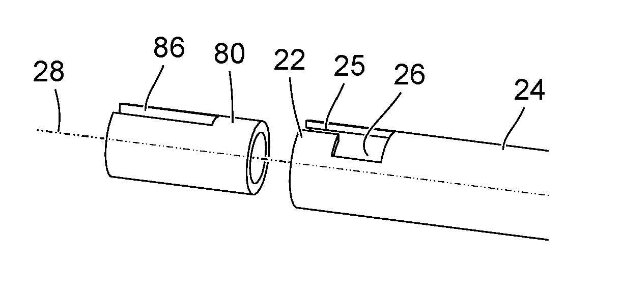
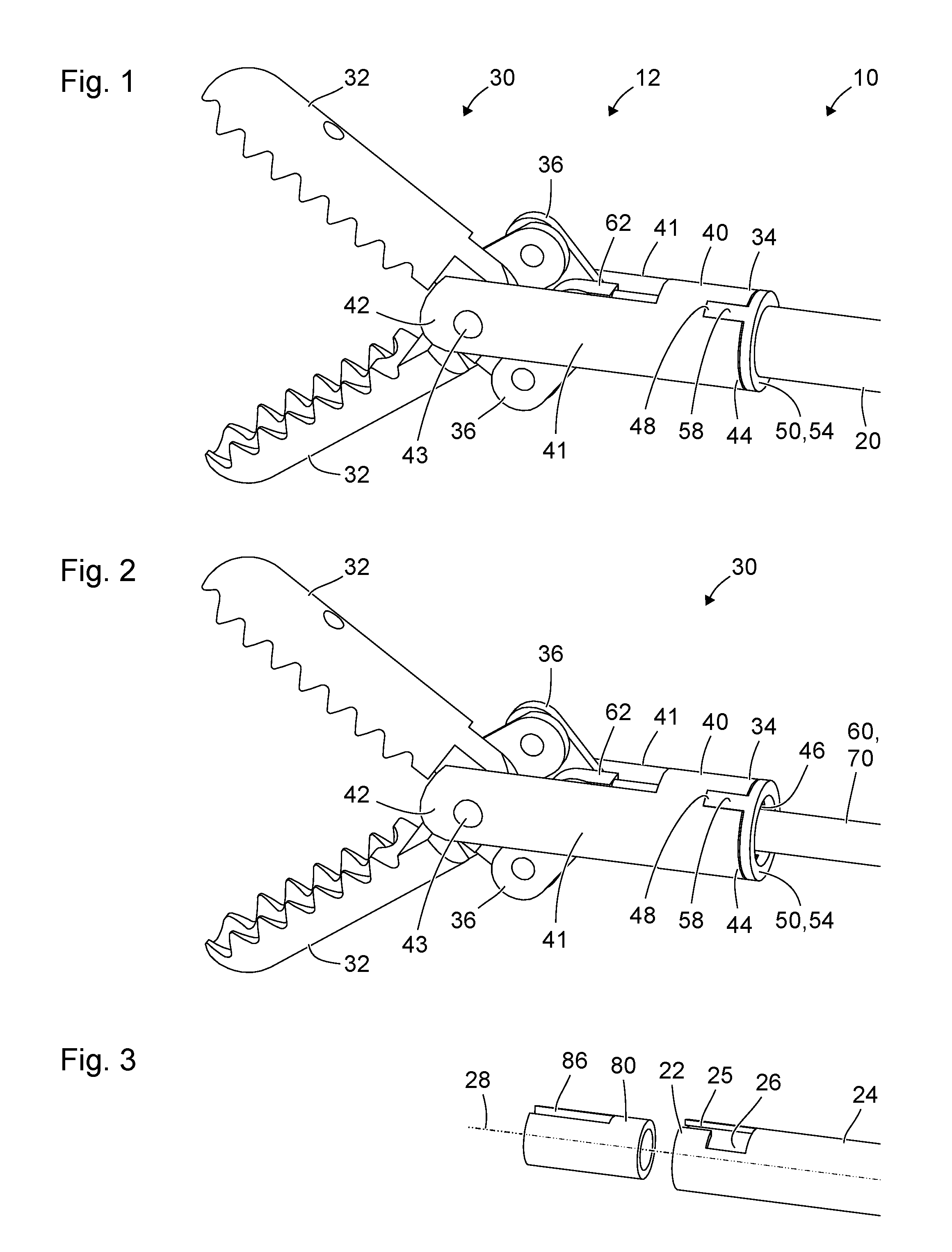
[0054]FIG. 1 shows a schematic axonometric view of a distal end 12 of a medical instrument 10 for micro-invasive applications in human or veterinary medicine. The medical instrument 10 has a long, thin, rigid or flexible (i.e. elastically deformable, or plastically deformable without destruction), straight or curved shank 20. The distal of the shank 20 is mechanically connected to a tool 30, in particular to the proximal end 34 thereof, in such a way as to be releasable without destruction. A manipulation mechanism for manually manipulating the medical instrument 10 can be provided at the proximal end of the shank 20.
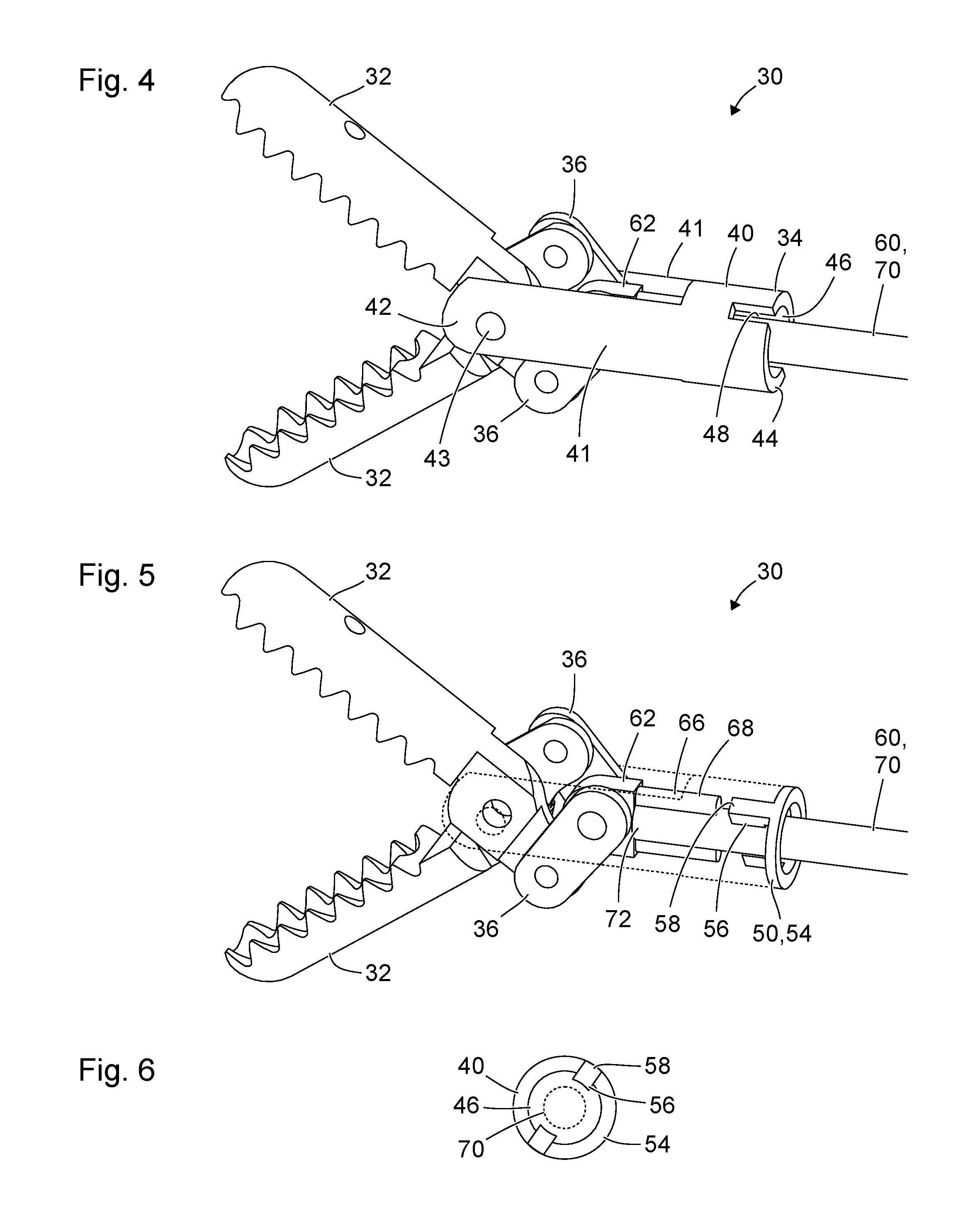
[0055]The tool 30 comprises two branches 32 which are pivotable in opposite directions about the same pivot axis and which serve for the gripping, pinching, electrosurgical coagulation or cutting of tissue. The tool 30 comprises a first component or fork component 40 and a second component or catch component 50. The fork component 40 comprises two parallel side rails 41...
PUM
 Abstract
Description
Claims
Application Information