Transmission Device with a Hydraulic System

a transmission device and hydraulic technology, applied in mechanical devices, fluid gearings, gearing, etc., can solve the problems of impaired actuator dynamics of the transmission device and impair the desired high dynamic of the transmission device, and achieve the effect of high dynami

Inactive Publication Date: 2017-01-12
ZF FRIEDRICHSHAFEN AG
View PDF3 Cites 6 Cited by
  • Summary
  • Abstract
  • Description
  • Claims
  • Application Information

AI Technical Summary

Benefits of technology

[0005]As such, exemplary aspects of the present invention provide a transmission device with a hydraulic system, with which a hydraulic supply of a torque converter is ensured, and which can be operated with desired high dynamics.

Problems solved by technology

However, disadvantageously, during unsaturated operating states of the primary pressure circuit of the hydraulic system, this leads to the fact that function groups of the transmission device to be provided with hydraulic fluid by the primary pressure circuit, that is, in addition to the converter lock-up clutch and additional transmission components, such as switching elements and the like, including a cooling device of the three-line converter in a normal operating state and in a closed operating state of the converter lock-up clutch, are not subjected to hydraulic fluid in the necessary extent under certain circumstances.
In addition, actuator dynamics of the transmission device are impaired by the additional supply of the three-line converter through the primary pressure circuit with the converter lock-up clutch subjected to operating pressure.
The volume flow of hydraulic fluid removed from the primary pressure circuit in the direction of the three-line converter can be compensated for by increasing, for example, a volume flow of hydraulic fluid made available through a main transmission pump; however, the additional supply of the hydraulic system of the transmission device takes place through the main transmission pump in a delayed extent, which impairs the desired high dynamics of a transmission device.

Method used


Image

  • Transmission Device with a Hydraulic System
  • Transmission Device with a Hydraulic System
  • Transmission Device with a Hydraulic System

Examples


Embodiment Construction

[0027]Reference will now be made to embodiments of the invention, one or more examples of which are shown in the drawings. Each embodiment is provided by way of explanation of the invention, and not as a limitation of the invention. For example, features illustrated or described as part of one embodiment can be combined with another embodiment to yield still another embodiment. It is intended that the present invention include these and other modifications and variations to the embodiments described herein.

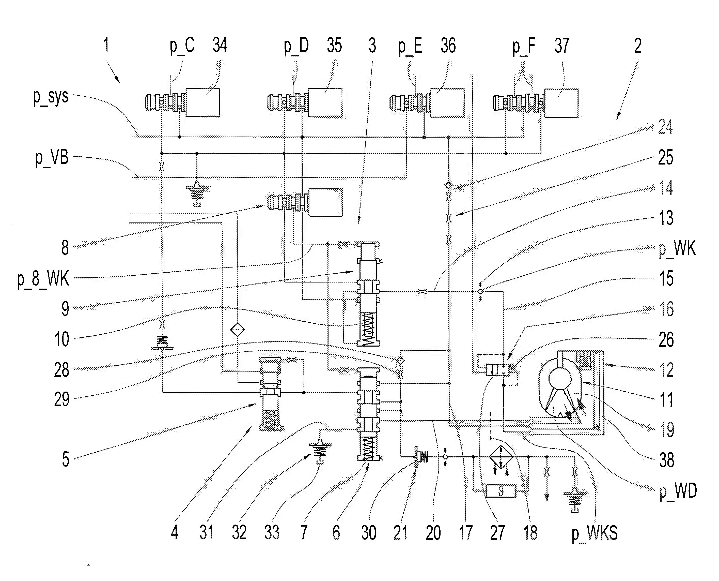
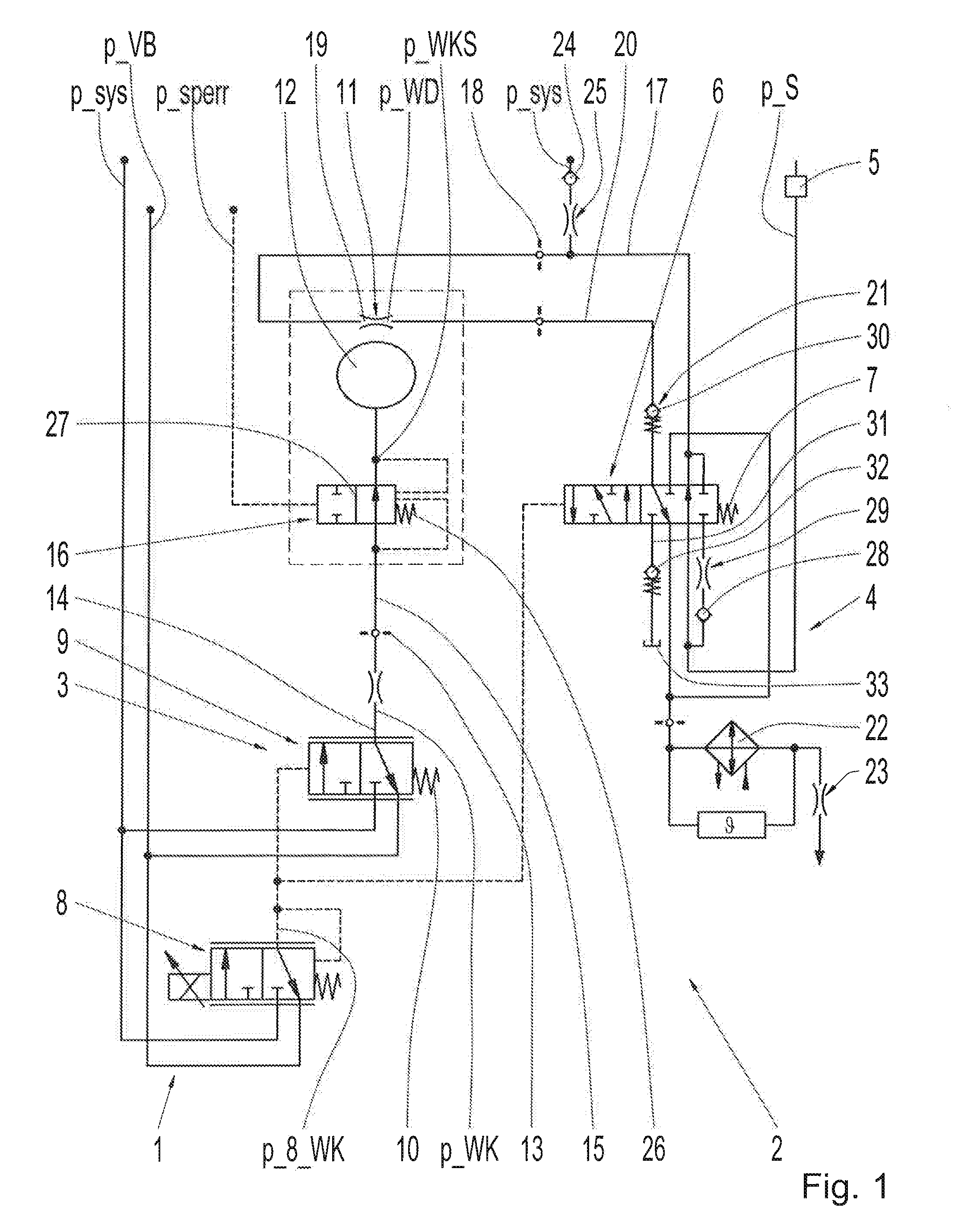
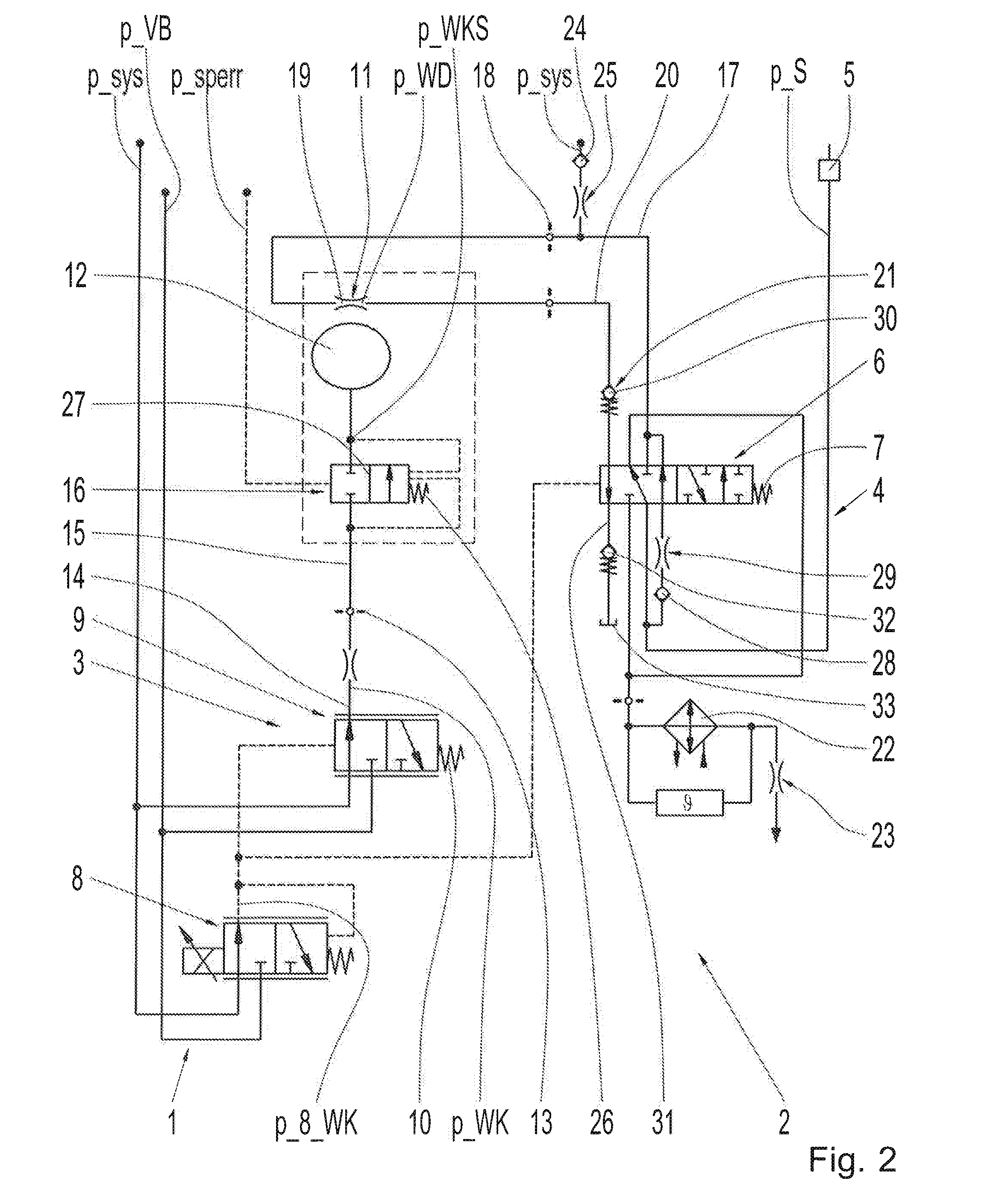
[0028]FIG. 1 shows a part of a hydraulic diagram of a hydraulic system 1 of a transmission device 2, whereas the hydraulic system 1 is designed with a primary pressure circuit 3 and a secondary pressure circuit 4. From a defined saturation condition of the primary pressure circuit 3, the secondary pressure circuit 4 can be supplied with hydraulic fluid. A pressure p_sys of the primary pressure circuit 3 is adjusted in the area of a system pressure valve (not shown in more detail)....


PUM


Abstract

A hydraulic system for a transmission device includes a primary pressure circuit and a secondary pressure circuit suppliable with hydraulic fluid from a defined saturation condition of the primary pressure circuit. A converter lock-up clutch is subjected to an operating pressure by a converter clutch valve. An inner torus chamber is suppliable with hydraulic fluid at a converter pressure of the secondary pressure circuit by a converter switching valve and by a valve device and a throttle device of the primary pressure circuit. The throttle device of the primary pressure circuit is downstream of the valve device of the primary pressure circuit.

Description

FIELD OF THE INVENTION[0001]The invention relates generally to a transmission device with a hydraulic system.BACKGROUND[0002]From DE 10 2007 000 561 A1, a transmission device with a hydraulic system is known; the transmission device includes a primary pressure circuit and a secondary pressure circuit. The secondary pressure circuit can be supplied with hydraulic fluid from a defined saturation condition of the primary pressure circuit. In addition, the transmission device is designed with a hydrodynamic torque converter formed with a “three-line converter” and a converter lock-up clutch corresponding to the hydrodynamic torque converter. The converter lock-up clutch is actuated through the primary pressure circuit with an operating pressure that is adjustable in the area of the converter clutch valve. In the open operating state of the converter lock-up clutch, an inner torus chamber of the three-line converter is subjected to a converter pressure that is adjustable in the area of t...

Claims


Application Information

Patent Timeline
Patent Type & Authority Applications(United States)
IPC IPC(8): F16H45/02F16D48/02F16H61/14
CPCF16H45/02F16D25/14F16H61/14F16H61/0206F16H61/143
Inventor HERRMANN, MARKUSSCHMIDT, THILO
Owner ZF FRIEDRICHSHAFEN AG
Why Eureka
Try Eureka