Cooling device and multi-chamber heat treatment device

Inactive Publication Date: 2017-01-26
IHI CORP +1
View PDF0 Cites 1 Cited by
  • Summary
  • Abstract
  • Description
  • Claims
  • Application Information

AI Technical Summary

Benefits of technology

[0011]According to the present disclosure, in the cooling chamber, the coolant is supplied from below the article to be treated by the supply nozzle, the supplied coolant is collected from above the article to be treated by the recovery pipeline, and the collected coolant is pumped to the supply nozzle by the pump. For this reason, according to the present disclosure, a flow from below to above is formed in the cooling chamber by the supply nozzle, the recovery pipeline and the pump. Since such a flow is directed in the same direction as the coolant heated by cooling the article to be treated, generation of turbulence in the flow of the coolant in the cool

Problems solved by technology

For this reason, in the above-mentioned method, a flow of the coolant supplied into the cooling chamber from the nozzle and a flow of the coolant that is heated to flow upward interfere with each other, the flow of the coolant in the cooling chamber becom

Method used


Image

  • Cooling device and multi-chamber heat treatment device
  • Cooling device and multi-chamber heat treatment device
  • Cooling device and multi-chamber heat treatment device

Examples


Embodiment Construction

[0018]Hereinafter, an embodiment of an embodiment of a cooling device and a multi-chamber heat treatment device according to the present disclosure will be described with reference to the accompanying drawings. Further, in the following drawings, in order to increase members to recognizable sizes, scales of the members may be appropriately exaggerated.

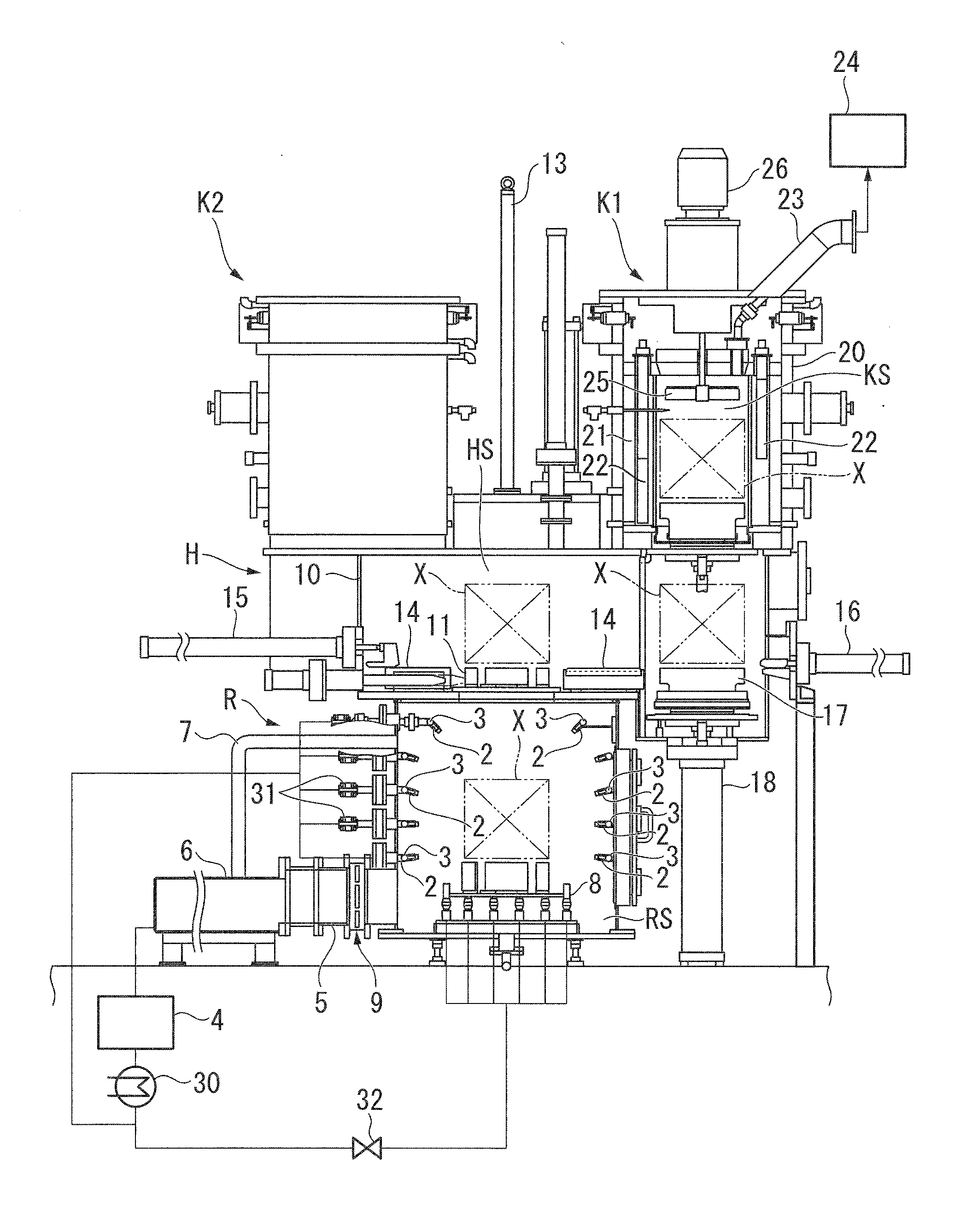
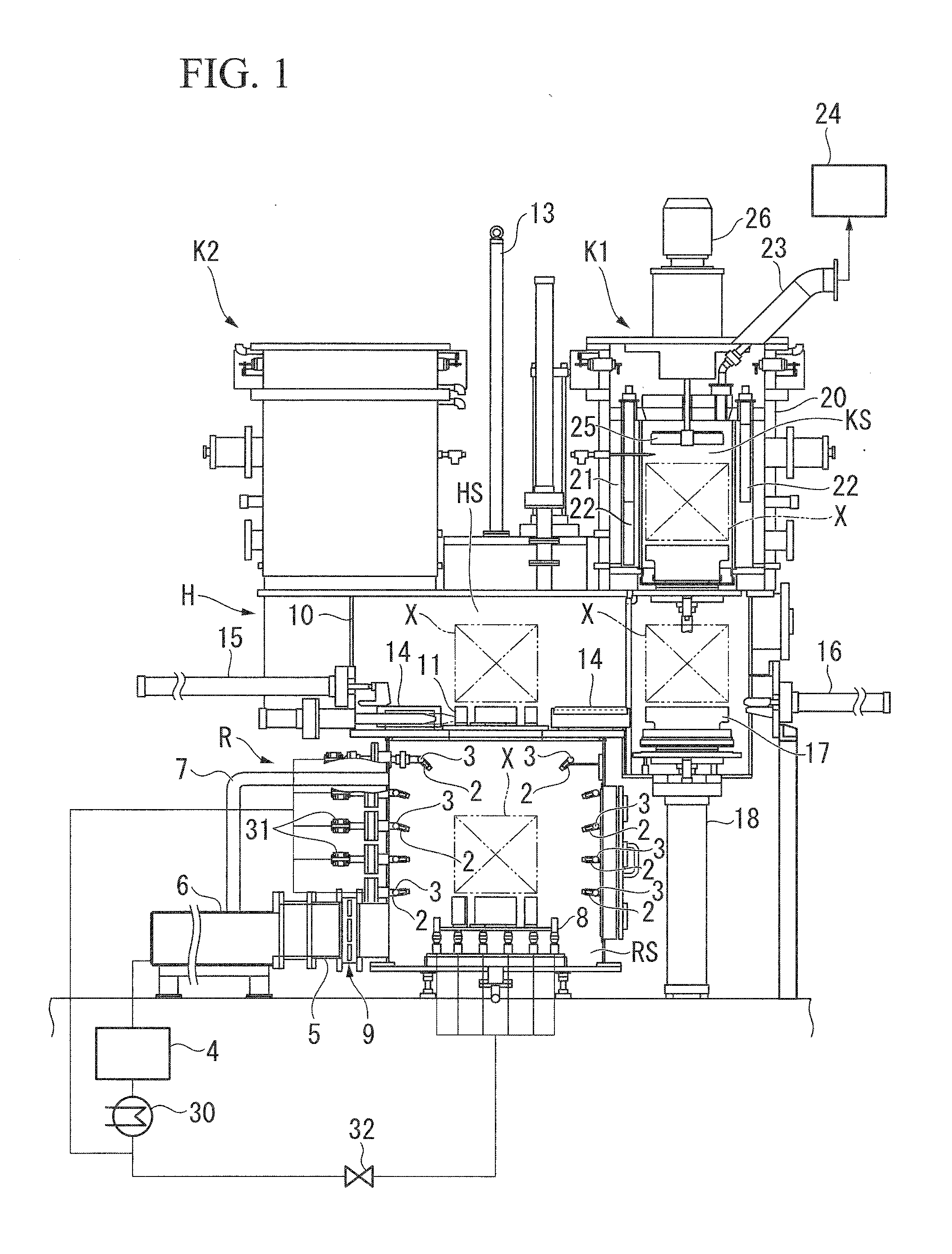
[0019]As shown in FIG. 1, a multi-chamber heat treatment device including a cooling device of the embodiment is a device in which a cooling device R, an intermediate conveyance device H, and two heating devices (a heating device K1 and a heating device K2) are integrated. Further, the number of heating devices may be three.

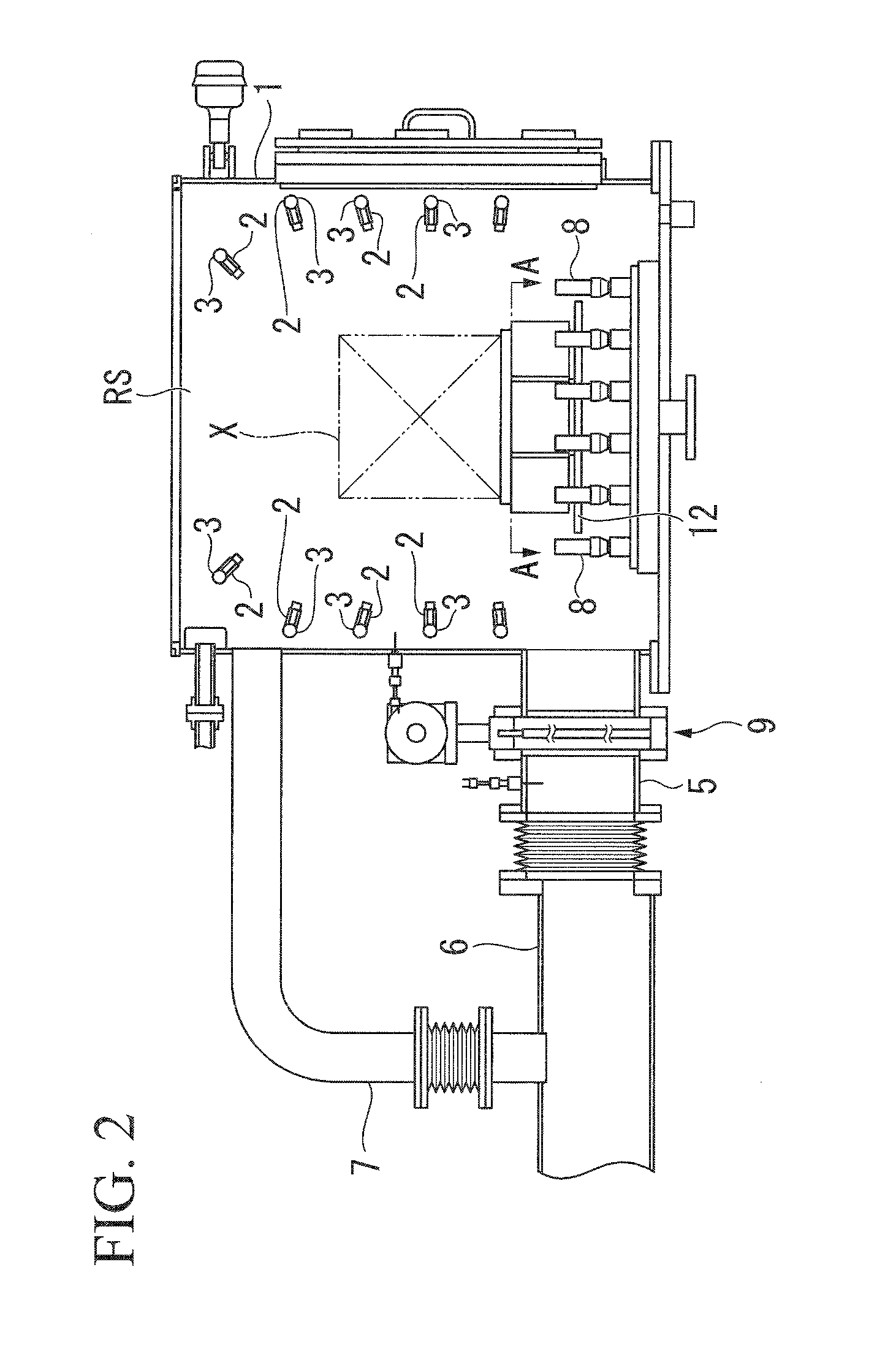
[0020]The cooling device R is a device configured to cool an article to be treated X, and as shown in FIG. 1, includes a cooling chamber 1, a plurality of cooling nozzles 2, a plurality of mist headers 3, a cooling pump 4 (a pump), a cooling drain pipe 5, a cooling water tank 6, a cooling circulation pipe 7 (a recove...


PUM


Abstract

A cooling device configured to cool an article to be treated by immersing the article to be treated in coolant includes a cooling chamber configured to accommodate the article to be treated and store the coolant therein, a supply nozzle configured to supply the coolant into the cooling chamber from below the article to be treated, a recovery pipeline configured to collect the coolant stored in the cooling chamber from above the article to be treated, and a pump configured to pump the coolant collected by the recovery pipeline to the supply nozzle.

Description

CROSS-REFERENCE TO RELATED APPLICATIONS[0001]The present application is a continuation application of International Application No. PCT / JP2015 / 069889, filed Jul. 10, 2015, which claims priority to Japanese Patent Application No. 2014-152048, filed Jul. 25, 2014. The contents of these applications are incorporated herein by reference in their entirety.TECHNICAL FIELD[0002]The present disclosure relates to a cooling device and a multi-chamber heat treatment device.BACKGROUND[0003]For example, Patent Document 1 discloses a multi-chamber heat treatment device including three heating devices and a single cooling device. In the multi-chamber heat treatment device, the heating devices and the cooling device are connected via intermediate conveyance chambers, and for example, an article to be treated heated by the heating devices is conveyed to the cooling device and cooled therein. In such a cooling device, for example, cooling of the article to be treated is performed by storing a coolant...

Claims


Application Information

Patent Timeline
IPC IPC(8): C21D1/667
CPCC21D1/667C21D1/18C21D1/64F27D9/00
Inventor KATSUMATA, KAZUHIKOISOMOTO, KAORUNAGATA, TAKAHIRONAKAYAMA, AKIRASHIMIZU, YUUSUKENISHITANI, GEN
Owner IHI CORP
Why Eureka
Try Eureka