Military vessel

a technology for military vessels and resonant antennas, applied in the direction of collapsable antennas, offensive equipment, resonant antennas, etc., can solve the problem of limited weapon directing range, and achieve the effect of increasing the weapon directing rang

Active Publication Date: 2017-10-19
THYSSENKRUPP MARINE SYST GMBH +1
View PDF4 Cites 3 Cited by
  • Summary
  • Abstract
  • Description
  • Claims
  • Application Information

AI Technical Summary

Benefits of technology

[0004]Against this background, it is the object of the present invention to increase the directing range of the weapon.

Problems solved by technology

With such military vessels, it has been found to be a disadvantage that the directing range of the weapon is limited by the antenna usually protruding high above the hull of the vessel.

Method used


Image

  • Military vessel
  • Military vessel
  • Military vessel

Examples


Embodiment Construction

[0035]In the various figures, identical parts are always provided with the same reference characters and as a rule are therefore also only named or mentioned once in each case.

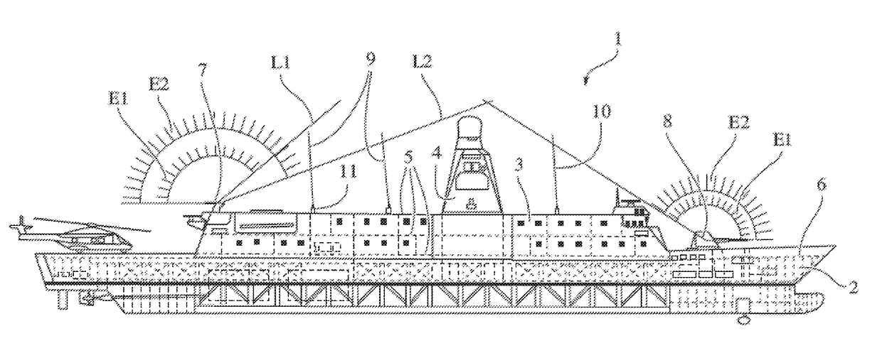
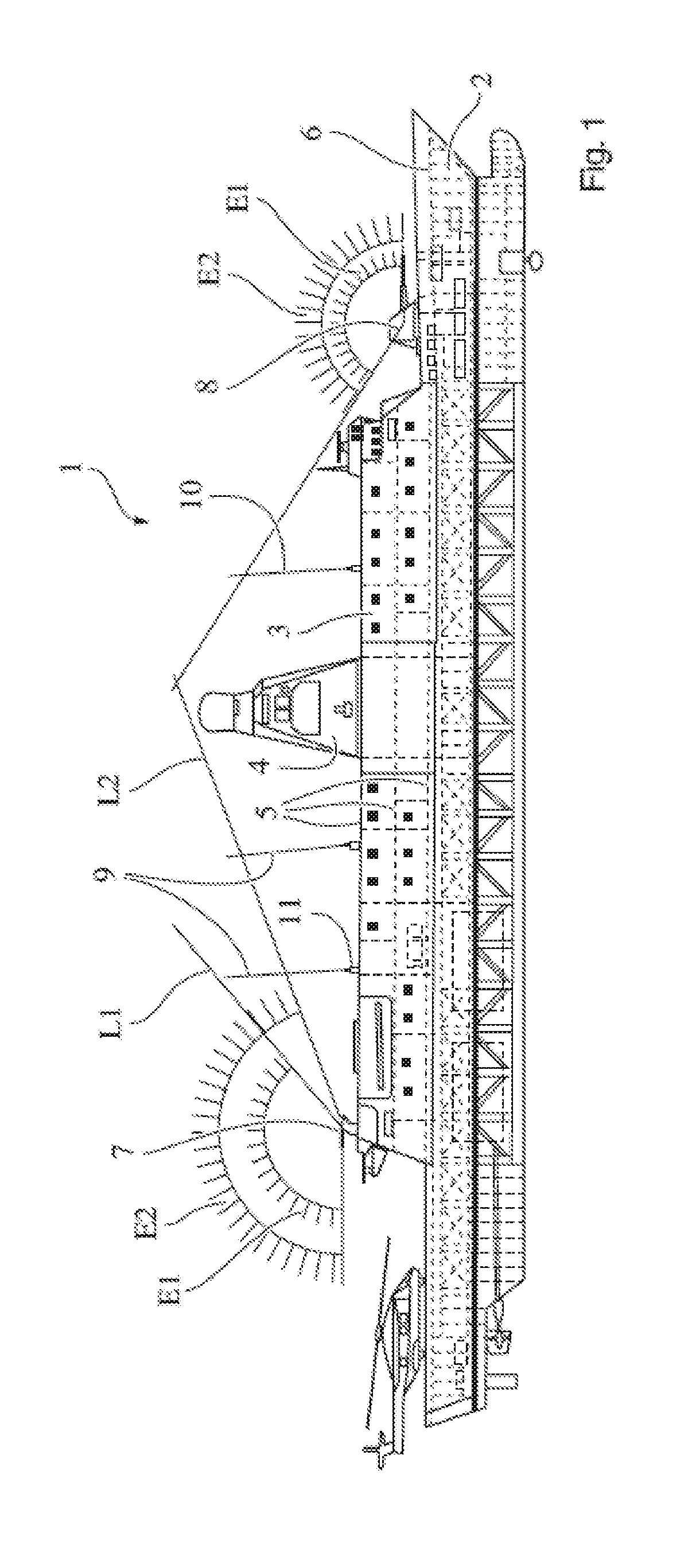
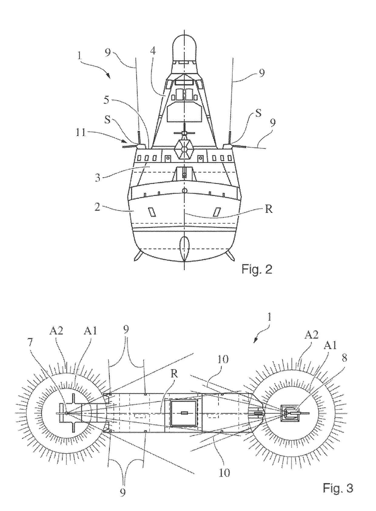
[0036]In FIG. 1, a military vessel 1 in the form of a surface vessel is represented. The vessel 1 comprises a hull 2, above which a main deck 6 is provided. On the main deck 6 there is a structure 3 of the vessel 1 comprising a plurality of decks 5. A tower 4 is provided on the structure 3. As protective equipment, the vessel 1 comprises a first directable weapon 7 that is disposed on an upper deck 5 in the region of the stern. Furthermore, a second directable weapon 8 is provided in the region of the bow on a main deck 6. The directable weapons 7, 8 are preferably directable in azimuth and / or elevation. According to the exemplary embodiment, the weapons 7, 8 are in the form of guns.

[0037]In order to be able to communicate with other vessels and / or a control station, the vessel 1 comprises a plurality of anten...


PUM


Abstract

A military vessel may include a directable weapon and an antenna. The antenna can be swiveled from a first position, in which the antenna is disposed essentially vertically, into a second position, in which a height of the antenna above the military vessel is reduced to increase a directing range of the directable weapon compared to the first position. A method for operating a military vessel with a directable weapon and an antenna may involve swiveling the antenna from a first position, in which the antenna is disposed essentially vertically, into a second position, in which the height of the antenna above the vessel is reduced to increase the directing range of the weapon compared to the first position.

Description

PRIOR ART[0001]The present invention concerns a military vessel with a directable weapon and an antenna. The invention further concerns a method for operating a military vessel with a directable weapon and an antenna.[0002]Such military vessels can for example be in the form of frigates, corvettes, patrol ships, aircraft carriers or helicopter carriers. For defense, weapons that are directable in azimuth and / or elevation, such as for example guns or launchers, are usually provided on the decks of such ships. Furthermore, as a rule such military vessels comprise antennas, by means of which the vessels can communicate with other aircraft or with vessels or with a control station, or by means of which awareness measures can be carried out. US 2013 / 0 300 620 A1 discloses an apparatus for remotely controlled erecting and laying down of an antenna of a vessel. KR 10 2009 0 072 252 A discloses a system for automatically adjusting the height of a radar or radio mast of a ship. U.S. Pat. No....

Claims


Application Information

Patent Timeline
Patent Type & Authority Applications(United States)
IPC IPC(8): F41A27/02H01Q1/42H01Q1/22H01Q1/34H01Q3/08H01Q1/52
CPCF41A27/02H01Q1/428H01Q1/22H01Q3/08H01Q1/52H01Q1/34F41A17/08H01Q1/084H01Q9/32B63B2201/20B63G1/00
Inventor OESMANN, HANSEWERS, DIRK
Owner THYSSENKRUPP MARINE SYST GMBH
Why Eureka
Try Eureka