Mitral heart valve replacement

a heart valve and mitral valve technology, applied in the field of heart valve replacement, can solve problems such as serious health complications

Active Publication Date: 2017-11-16
ST JUDE MEDICAL CARDILOGY DIV INC
View PDF2 Cites 51 Cited by
  • Summary
  • Abstract
  • Description
  • Claims
  • Application Information

AI Technical Summary

Problems solved by technology

Diseased and/or defective heart valves m

Method used


Image

  • Mitral heart valve replacement
  • Mitral heart valve replacement
  • Mitral heart valve replacement

Examples


Embodiment Construction

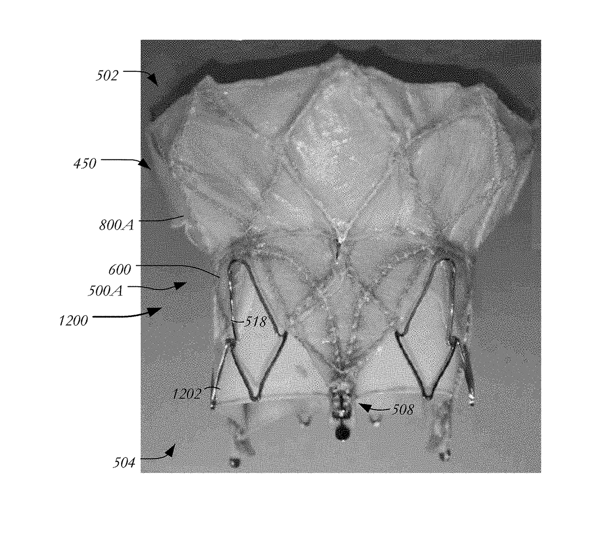
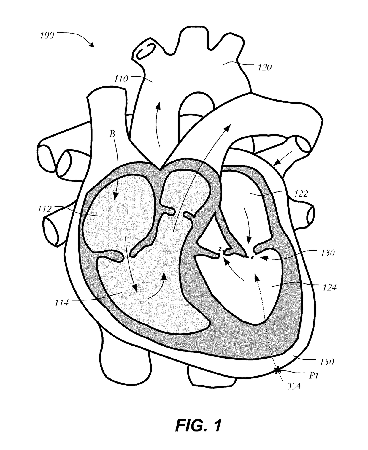
[0034]In conventional collapsible prosthetic heart valves, the stent is usually anchored within the native valve annulus via radial forces exerted by the expanding stent against the native valve annulus. If the radial force is too high, damage may occur to heart tissue. If, instead, the radial force is too low, the heart valve may move from its implanted position, for example, into the left ventricle. Because such anchoring partly depends on the presence of calcification or plaque in the native valve annulus, it may be difficult to properly anchor the valve in locations where plaque is lacking (e.g., the mitral valve annulus). Additionally, in certain situations it may be preferable to restore native valve leaflet function rather than implanting a prosthetic device to replace that function.

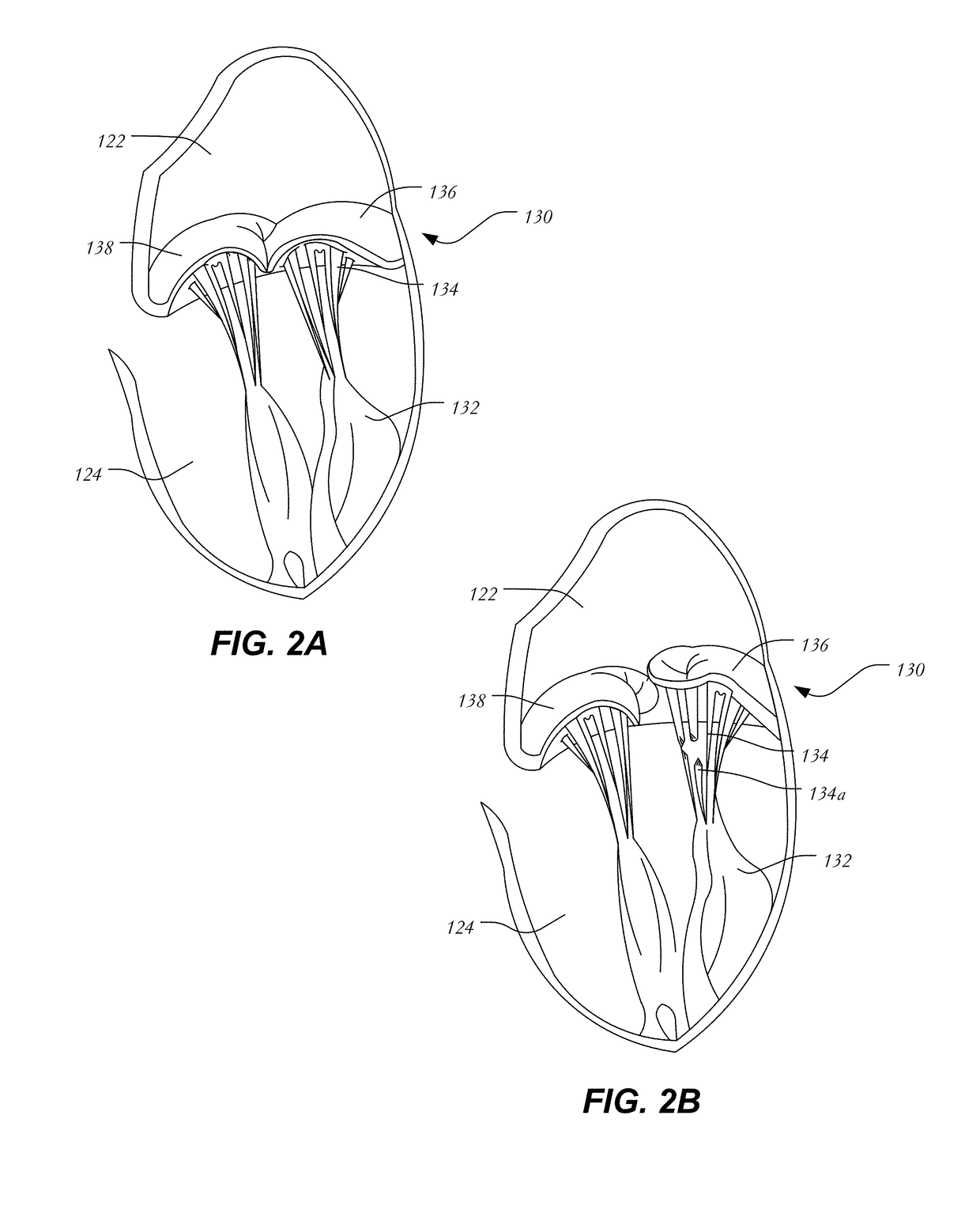
[0035]In view of the foregoing, there is a need for further improvements to the devices, systems, and methods for replacing the function of a native heart valve, such as a mitral valve, a tricuspi...


PUM


Abstract

A prosthetic heart valve having an inflow end, an outflow end and a longitudinal axis extending from the inflow end to the outflow end includes a collapsible and expandable stent including a plurality of cells arranged in at least one row extending around a circumference of the stent. The stent further includes at least one engaging arm joined to one of the cells adjacent the outflow end and having a free end extending toward the inflow end, the engaging arm being movable between a loaded condition in which the engaging arm is oriented substantially parallel with the longitudinal axis of the stent, a partially-released condition in which the engaging arm forms a first angle with the longitudinal axis of the stent, and a fully-released condition in which the engaging arm forms a second angle with the longitudinal axis of the stent, the first angle being larger than the second angle.

Description

CROSS-REFERENCE TO RELATED APPLICATIONS[0001]The present application claims the benefit of the filing date of U.S. Provisional Patent Application No. 62 / 335,294 filed May 12, 2016, the disclosure of which is hereby incorporated herein by reference.BACKGROUND OF THE INVENTION[0002]The present disclosure relates to heart valve replacement and, in particular, to collapsible prosthetic heart valves. More particularly, the present disclosure relates to devices and methods for replacing the functionality of a native mitral valve.[0003]Diseased and / or defective heart valves may lead to serious health complications. One method of addressing this condition is to replace a non-functioning heart valve with a prosthetic valve. Prosthetic heart valves that are collapsible to a relatively small circumferential size can be delivered into a patient less invasively than valves that are not collapsible. For example, a collapsible valve may be delivered into a patient via a tube-like delivery apparatu...

Claims


Application Information

Patent Timeline
IPC IPC(8): A61F2/24
CPCA61F2/2418A61F2210/0014A61F2220/0008A61F2/2412A61F2250/006
Inventor DALE, THEODORE PAULAHMANN, KATHERINE A.PERSZYK, BRIAN JOSEPHGLIMSDALE, MATHIAS CHARLESVIETMEIER, KRISTOPHER HENRY
Owner ST JUDE MEDICAL CARDILOGY DIV INC
Why Eureka
Try Eureka