Diffuser-type endplate propeller

a technology of endplate and propeller, which is applied in the direction of propeller parts, waterborne vessels, vessel construction, etc., can solve the problems of reducing the probability of cavitation on the low-pressure side of the propeller, generating hull vibration and noise, and reducing the efficiency of the propeller

Active Publication Date: 2018-05-10
HUNG SHEN PROPELLER CO LTD
View PDF5 Cites 2 Cited by
  • Summary
  • Abstract
  • Description
  • Claims
  • Application Information

AI Technical Summary

Benefits of technology

[0006]Accordingly, the present invention is directed to a diffuser-type endplate propeller under an inclined-shaft inflow condition which can largely reduce even eliminate the sheet cavitation phenomenon produced by the endplate itself regardless of the propeller blades turning to any angle positions.

Problems solved by technology

Accordingly, a quite portion of the thrust produced by the above-mentioned TVF propeller or CLT propeller is provided by the high-pressure side-surfaces of the propeller blades, which reduces the probability for the low-pressure side-surface of the propeller to produce cavitation.
In fact, however, it is found when the CLT propeller rotates under the uniform inflow condition, the sheet cavitation phenomenon is always produced at the outer-sides of the endplate regardless of a propeller blade turning to any circumferential position so as to rise up the resistance on the endplate and reduce the efficiency of the propeller.
As a result, it may generate the hull vibration and noise.
Obviously, it is quite unhelpful for a low-vibration and low-noise design of ship.
Another more serious trouble is that if a CLT propeller is applied to a hull based on the inclined-shaft design, for example, a speedboat, the CLT propeller under an inclined-shaft inflow condition has a more serious cavitation phenomenon occurred at the endplate of a blade when the blade turns to the upper-vertical position.

Method used


Image

  • Diffuser-type endplate propeller
  • Diffuser-type endplate propeller
  • Diffuser-type endplate propeller

Examples


Embodiment Construction

[0032]In the following, the depicted embodiments together with the included drawings are intended to explain the feasibility of the present invention, wherein for better understanding and clear illustrating, the proportions or the angles between parts are amplified or shrunk appropriately so that the proportions or the angles herein are to describe, not to limit, the present invention.

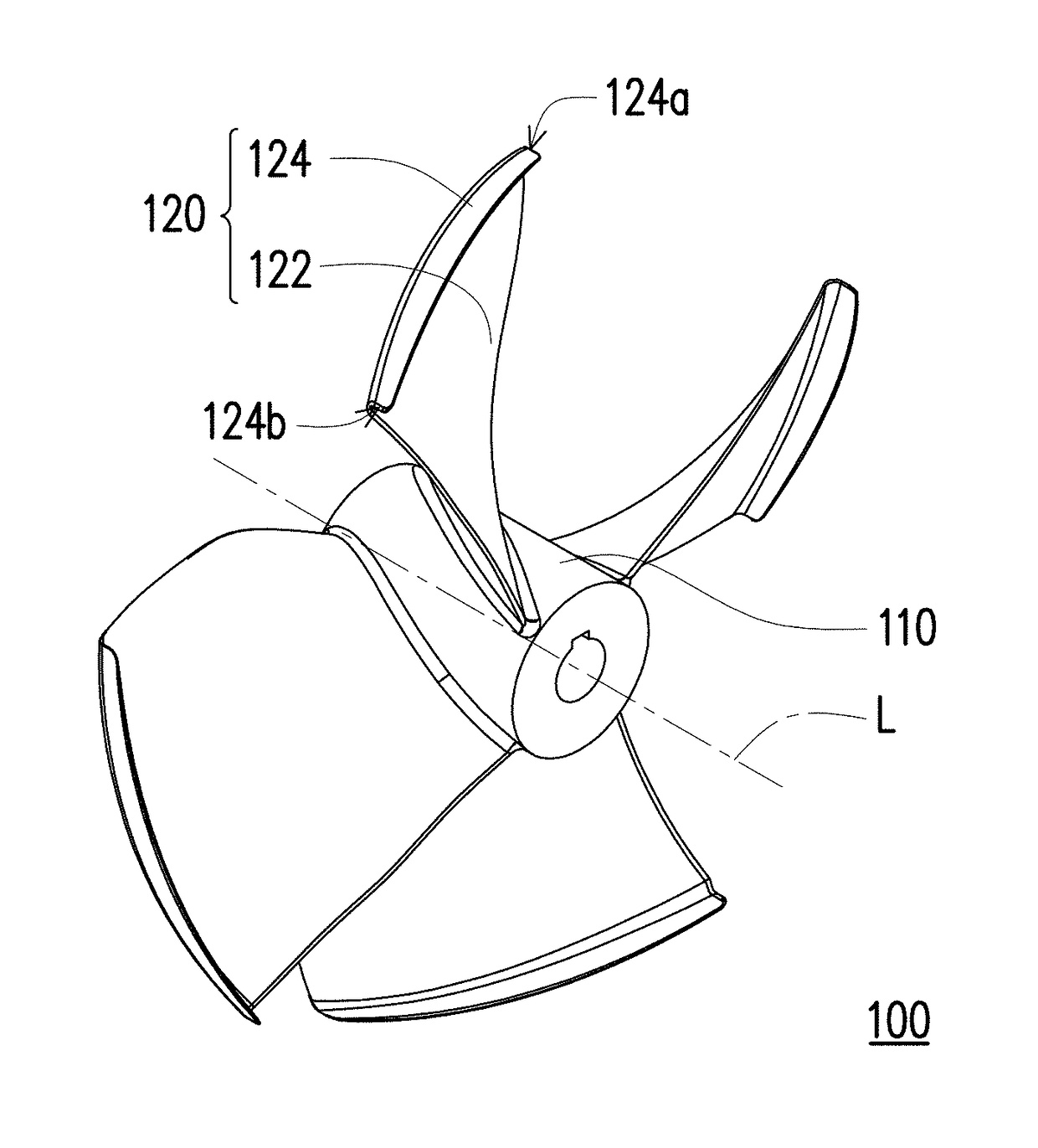
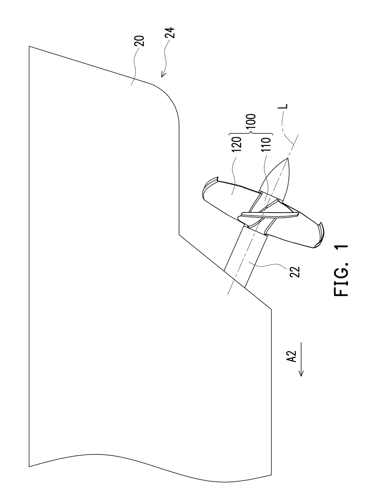
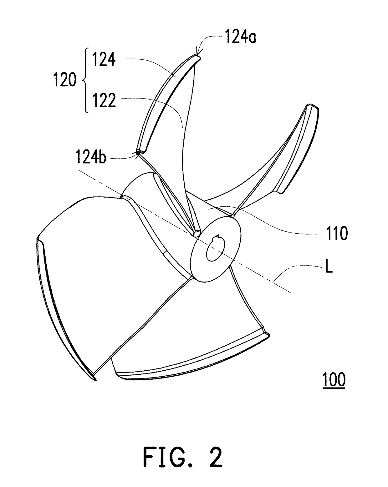
[0033]FIG. 1 is a schematic partial diagram showing a diffuser-type endplate propeller connected to a hull in an embodiment of the invention, FIG. 2 is a three-dimensional diagram of the diffuser-type endplate propeller of FIG. 1, FIG. 3A is a front-view diagram of the diffuser-type endplate propeller in FIG. 1 in the angle of view towards the stern of the hull, and FIG. 3B is a cross-sectional view along the section line I-I′ of the diffuser-type endplate propeller in FIG. 3A. Referring to FIGS. 1-3B, a diffuser-type endplate propeller 100 of the embodiment is able to drive a hull 20, and the diffuser...


PUM


Abstract

A diffuser-type endplate propeller driving a hull and including a propeller hub a plurality of blades is provided. The propeller hub has an axis of rotation and is connected to a transmission shaft of the hull. The blade has a blade-body and an endplate. The blade-body is connected to the propeller hub and extends outward from the propeller hub to the corresponding endplate, the endplate bends from the corresponding blade-body to extend towards a stern of the hull, and the endplate has a leading edge and a trailing edge. A cylindrical surface is imaginarily formed by the leading edges while the diffuser-type endplate propeller is rotated about the axis. Each of the endplates has a first tangent plane at the leading edge thereof, the cylindrical surface has a second tangent plane at the leading edge. An included angle is measured from the second tangent plane to the first tangent plane.

Description

CROSS-REFERENCE TO RELATED APPLICATION[0001]This application is a continuation-in-part application of and claims the priority benefit of U.S. application Ser. No. 14 / 151,827, filed on Jan. 10, 2014, now pending, which claims the priority benefit of Taiwan application serial no. 102120356, filed on Jun. 7, 2013. The entirety of each of the above-mentioned patent applications is hereby incorporated by reference herein and made a part of this specification.BACKGROUND OF THE INVENTIONField of the Invention[0002]The present invention generally relates to a propeller, and more particularly, to a diffuser-type endplate propeller.Description of Related Art[0003]Most of the current ships use propellers to drive fluid to produce sail powers. Specifically, when a propeller blade rotates, there is a pressure difference existing between a high-pressure side-surface and a low-pressure side-surface of the propeller blade, and the pressure difference forms a thrust to make the ship proceed on the w...

Claims


Application Information

Patent Timeline
Patent Type & Authority Applications(United States)
IPC IPC(8): B63H1/26B63H1/20
CPCB63H1/26B63H1/20B63B2748/00B63H1/18B63H1/15B63H1/16
Inventor KEHR, YOUNG-ZEHR
Owner HUNG SHEN PROPELLER CO LTD
Why Eureka
Try Eureka