Multiple pumping luminescent rod configuration for obtaining ultra-high brightness

a luminescent rod and multi-pump technology, applied in semiconductor devices, lighting and heating apparatus, instruments, etc., can solve the problems of relatively difficult scalability for obtaining higher intensities, relatively long rods, and relatively difficult to produce, so as to reduce thermal stability and reduce thermal stability. the effect of the penalty

Active Publication Date: 2018-12-27
SIGNIFY HLDG BV
View PDF7 Cites 0 Cited by
  • Summary
  • Abstract
  • Description
  • Claims
  • Application Information

AI Technical Summary

Benefits of technology

[0045]However, when desired the luminescent concentrators that are used as pumps may also be configured under a non-perpendicular angle. Especially, each luminescent concentrator comprises a body axis (BA). Hence, in embodiments the plurality of first luminescent concentrators includes two or more subsets of first luminescent concentrators configured with an angle of the body axis (BA) of the first luminescent concentrator and the body axis (BA) of the second luminescent concentrator unequal to 90°, such as in the range of at least 5° to smaller than 90°, such as 15-45°. Angles unequal to 90° may especially be useful for low surface reflection.
[0046]In yet further embodiments, the elongated light transmissive body of one or more luminescent concentrators comprise an elongated ceramic body. For instance, luminescent ceramic garnets doped with Ce3+ (trivalent cerium) can be used to convert blue light into light with a longer wavelength, e.g. within the green to red wavelength region, such as in the range of about 500-750 nm. To

Problems solved by technology

One of the problems of this concept is related to the intensity of the LEDs used for pumping the luminescent waveguide.
However, this may

Method used


Image

  • Multiple pumping luminescent rod configuration for obtaining ultra-high brightness
  • Multiple pumping luminescent rod configuration for obtaining ultra-high brightness
  • Multiple pumping luminescent rod configuration for obtaining ultra-high brightness

Examples


Embodiment Construction

[0075]A light emitting device according to the invention may be used in applications including but not being limited to a lamp, a light module, a luminaire, a spot light, a flash light, a projector, a (digital) projection device, automotive lighting such as e.g. a headlight or a taillight of a motor vehicle, arena lighting, theater lighting and architectural lighting.

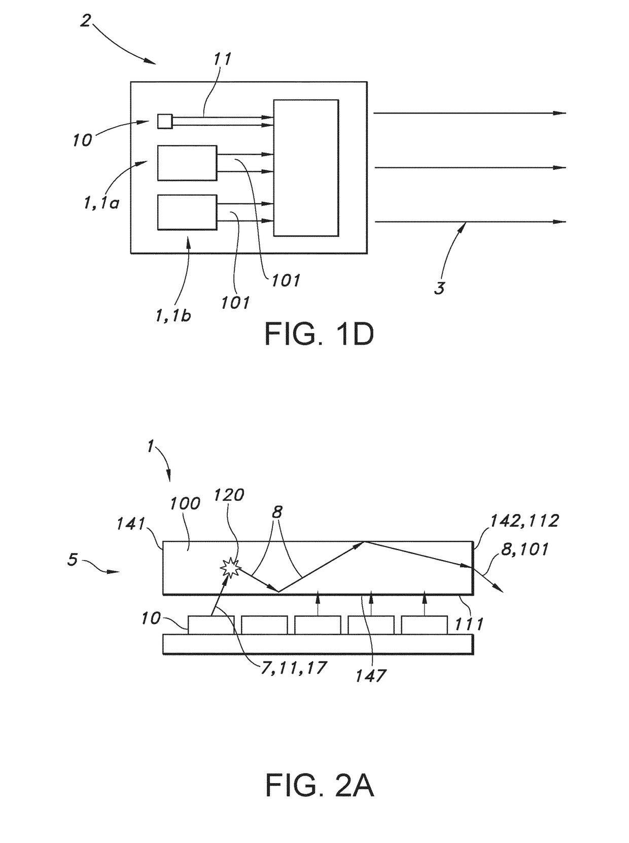
[0076]Light sources which are part of the embodiments according to the invention as set forth below, may be adapted for, in operation, emitting light with a first spectral distribution. This light is subsequently coupled into a light guide or waveguide; here the light transmissive body. The light guide or waveguide may convert the light of the first spectral distribution to another spectral distribution and guides the light to an exit surface.

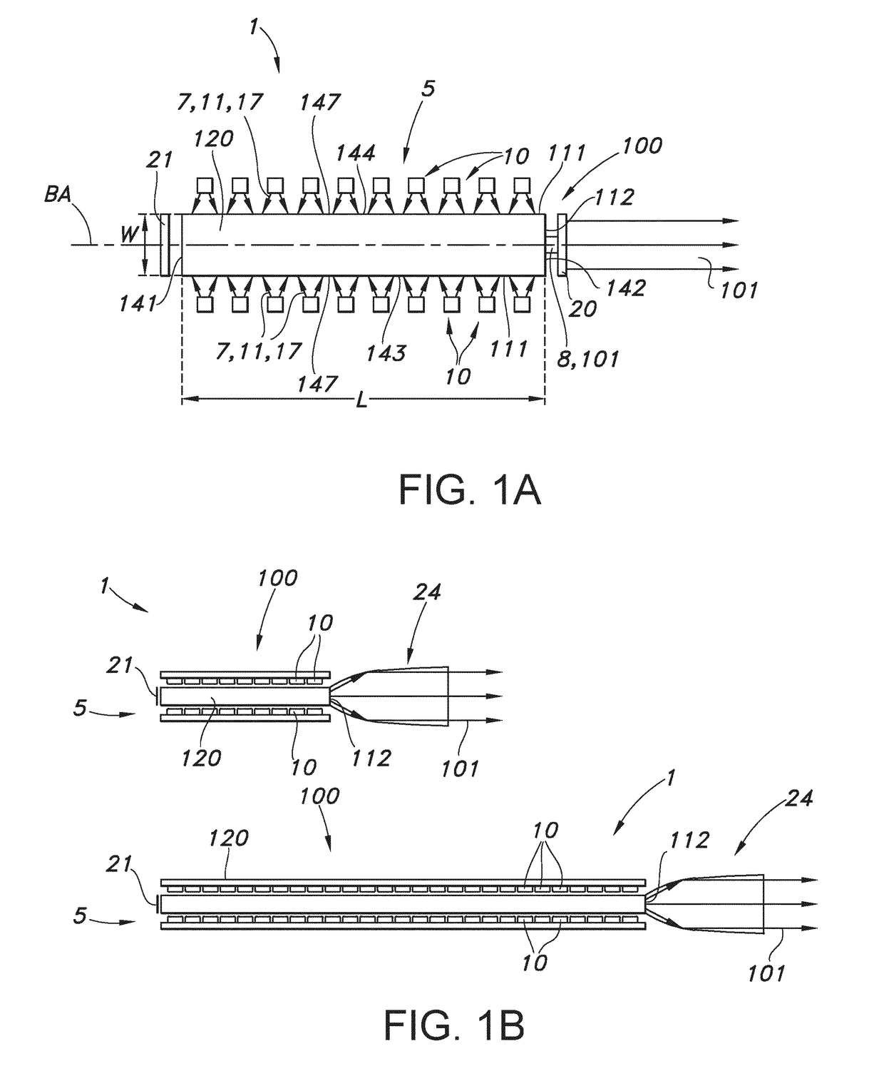
[0077]An embodiment of the lighting device as defined herein is schematically depicted in FIG. 1a. FIG. 1a schematically depicts a lighting device 1 comprising a plurality of solid...


PUM


Abstract

The invention provides multiple primary transparent luminescent light guides pumped with LEDs for pumping a secondary single transparent luminescent light guide from its sides for getting high light intensity from its light exit surface. Especially, the absorption and emission wavelength from the primary transparent light guides need to be lower than that of the secondary transparent luminescent light guide.

Description

FIELD OF THE INVENTION[0001]The invention relates to a lighting device, such as for use in a projector, or in automotive lighting or stage lighting.BACKGROUND OF THE INVENTION[0002]Luminescent rods are known in the art. WO2006 / 054203, for instance, describes a light emitting device comprising at least one LED which emits light in the wavelength range of >220 nm to <550 nm and at least one conversion structure placed towards the at least one LED without optical contact, which converts at least partly the light from the at least one LED to light in the wavelength range of >300 nm to ≤1000 nm, characterized in that the at least one conversion structure has a refractive index n of >1.5 and <3 and the ratio A:E is>2:1 and <50000:1, where A and E are defined as follows: the at least one conversion structure comprises at least one entrance surface, where light emitted by the at least one LED can enter the conversion structure and at least one exit surface, where light ...

Claims


Application Information

Patent Timeline
IPC IPC(8): F21K9/64F21V8/00F21K9/61F21K9/68F21K9/65
CPCF21K9/64G02B6/0055G02B6/0068G02B6/0026G02B6/0031F21K9/61F21K9/68F21K9/65G02B6/0003G02B6/005
Inventor VAN BOMMEL, TIESHIKMET, RIFAT ATA MUSTAFA
Owner SIGNIFY HLDG BV
Why Eureka
Try Eureka