Battery cell having dual welding structures

Active Publication Date: 2019-01-10
LG ENERGY SOLUTION LTD
View PDF0 Cites 4 Cited by
  • Summary
  • Abstract
  • Description
  • Claims
  • Application Information

AI Technical Summary

Benefits of technology

[0030]As described above, a battery cell according to the present disclosure have a structure in which an electrode tab junction formed on one side of each electrode group is electrically connected to an electrode lead via a conductive connecting member, and therefore it is possible to increase the energy density by shortening the length of the electro

Problems solved by technology

In order to solve this problem, in a process of shortening a length of the electrode tab, and bending the electrode tabs and tightly joining them to an electrode tab junction, stress is concentrated on the

Method used


Image

  • Battery cell having dual welding structures
  • Battery cell having dual welding structures
  • Battery cell having dual welding structures

Examples


Embodiment Construction

[0040]Hereinafter, embodiments of the present disclosure will be described with reference to the accompanying drawings. However, the description provided herein is for better understanding of the present disclosure, and the scope of the present disclosure is not limited thereto.

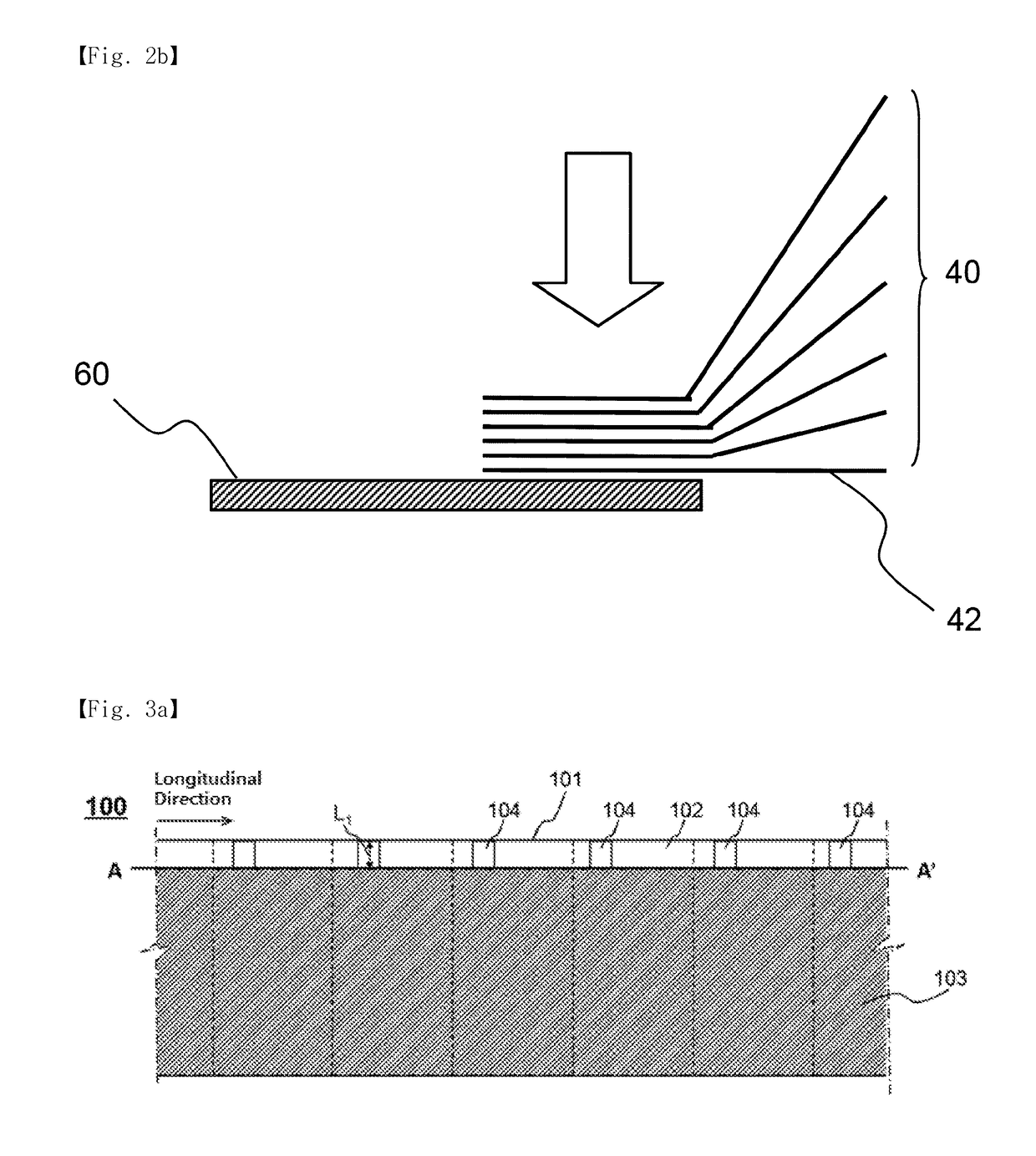
[0041]FIG. 3A illustrates a positive electrode prepared by applying a positive electrode active material to a positive electrode current collector included in an electrode group according to an embodiment of the present disclosure, and FIG. 3B illustrates a positive electrode prepared by applying a positive electrode active material to a positive electrode current collector included in a battery cell according to the related art.

[0042]Referring to FIG. 3A, a positive electrode 100 may be prepared by, in order for a non-coated part 102 to be formed in an upper portion adjacent to one end of a positive electrode current collector 101 in a longitudinal direction, applying a positive electrode active material 103...


PUM


Abstract

The present disclosure provides a battery cell including: two or more electrode groups having a structure in which electrodes including a positive electrode, a negative electrode, and a separator interposed between the positive electrode and the negative electrode are stacked, wherein each of the electrode groups includes an electrode tab junction on one side and is electrically connected to an electrode lead drawn to an outside of a battery case via a conductive connecting member, and has a structure including a first welding junction formed between one end of the conductive connecting member and the electrode tab junction and a second welding junction formed between the other end of the conductive connecting member and the electrode lead.

Description

TECHNICAL FIELD[0001]The present disclosure relates to a battery cell having dual welding structures.BACKGROUND ART[0002]As the use of fossil fuels has rapidly increased, the demand for the use of alternative energy, or clean energy, has increased. As a part of this trend, the field where research has been most actively conducted is electrochemical-based power generation and storage.[0003]At present, a typical example of an electrochemical device that utilizes electrochemical energy is a secondary battery, and the areas in which it is used are gradually increasing.[0004]Battery cells may be classified, on the basis of the shape of a battery case, into a cylindrical battery configured to have a structure in which an electrode assembly is mounted in a cylindrical metal container, a prismatic battery configured to have a structure in which an electrode assembly is mounted in a prismatic metal container, and a pouch-shaped battery configured to have a structure in which an electrode ass...

Claims


Application Information

Patent Timeline
IPC IPC(8): H01M2/26H01M2/06H01M2/30H01M50/179H01M50/533H01M50/536H01M50/54H01M50/548
CPCH01M2/26H01M2/30H01M2/06H01M10/04H01M10/0472Y02E60/10H01M50/54Y02P70/50H01M50/548H01M50/536H01M50/179H01M50/533H01M10/0436H01M10/0431H01M50/543H01M50/531
Inventor PARK, JONG PIL
Owner LG ENERGY SOLUTION LTD
Why Eureka
Try Eureka