Printing device, and method of controlling printing device

a printing device and printing technology, applied in printing, other printing devices, etc., can solve the problems of size growth and cost increase, and achieve the effect of reducing the number of signal lines needed

Inactive Publication Date: 2019-01-17
SII PRINTEK
View PDF3 Cites 0 Cited by
  • Summary
  • Abstract
  • Description
  • Claims
  • Application Information

AI Technical Summary

Benefits of technology

[0009]According to this configuration, by switching the settings of the input section which inputs the data to the drive circuit and the output sections which do not perform the output, it is possible to prevent the collision of the data, and therefore, it is possible to integrate the input sections and the output sections. Thus, according to this configuration, it is possible to reduce the number of the connection lines to the device for outputting data to the printing device, and thus, it is possible to achieve the reduction in size and cost of the printing device.
[0020]According to the invention, it is possible to reduce the number of signal lines necessary for the connection to the circuit board for controlling the head drive circuit.

Problems solved by technology

However, in the technology described in PLT 1, two sets of signal lines, namely a signal line for input and a signal line for output, are necessary, the number of the signal lines necessary for the connection to the circuit board for controlling the head drive circuit increases, and, for example, the number of pins of a connector for the connection increases to cause a problem of growth in size and increase in cost.

Method used


Image

  • Printing device, and method of controlling printing device
  • Printing device, and method of controlling printing device
  • Printing device, and method of controlling printing device

Examples


first embodiment

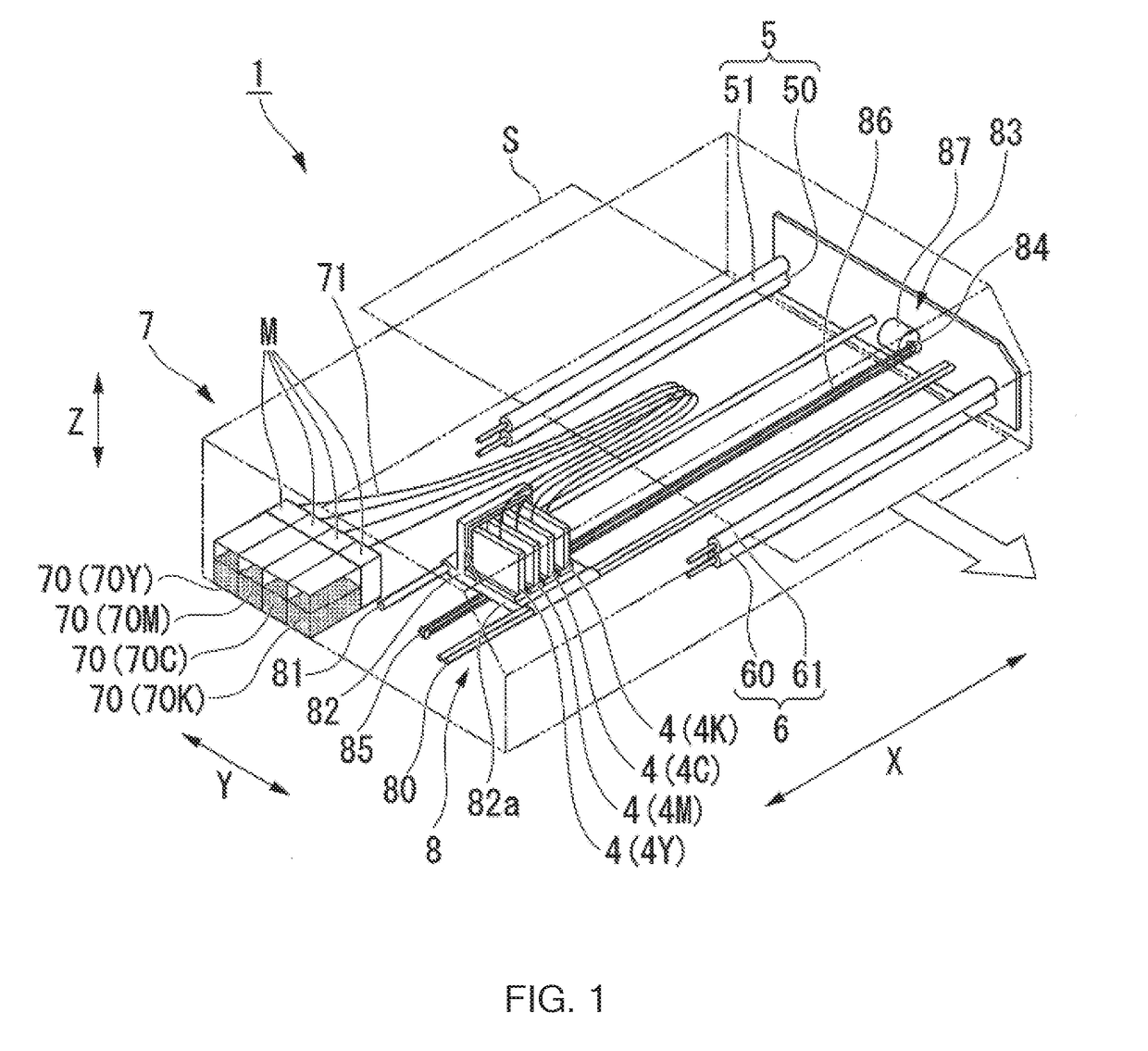
[0034]FIG. 1 is a perspective view of a printing device 1 according to a first embodiment of the invention.

[0035]As shown in FIG. 1, the printing device 1 is configured including a pair of conveying mechanisms 5, 6 for conveying a recording target medium S such as a paper sheet, liquid jet heads 4 for ejecting ink droplets to the recording target medium S, a liquid supply section 7 for supplying the liquid jet heads 4 with ink, and a scanning section 8 for making the liquid jet heads 4 perform a scanning operation in a direction (a sub-scanning direction) roughly perpendicular to a conveying direction (a main scanning direction) of the recording target medium S. It should be noted that the printing device 1 is, for example, an inkjet printer.

[0036]It should be noted that, in the following description, the sub-scanning direction is defined as an X direction, the main scanning direction is defined as a Y direction, and a direction perpendicular to both of the X direction and the Y dir...

second embodiment

Modified Example of Second Embodiment

[0145]Here, a modified example of the second embodiment will be described.

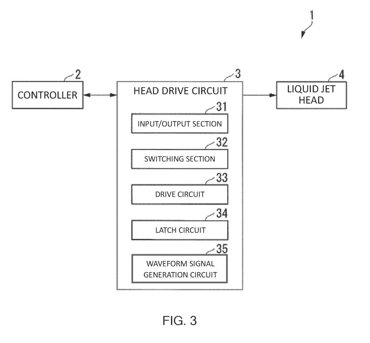
[0146]FIG. 11 is a block diagram showing a schematic configuration example of a printing device 1D according to the modified example of the present embodiment. As shown in FIG. 11, the printing device 1D is configured including a controller 2D, head drive circuits 3D (head drive circuits 31, 32, . . . , 3N-1, 3N), and liquid jet heads 41, 42, . . . , 4N-1, 4N.

[0147]It should be noted that in the example shown in FIG. 11, there is shown an example in which the head drive circuits 3 are each provided with one liquid jet head 4, but this example is not a limitation. The number of the liquid jet heads 4 can be two or more, for example, eight.

[0148]In the example shown in FIG. 11, the controller 2D outputs the data signal to the head drive circuits 31, 3N. In accordance with the switching signal, the head drive circuit 31 outputs the data signal to the head drive circuit 32, . ....


PUM


Abstract

The invention has an object of providing a printing device and a method of controlling the printing device each capable of reducing the number of signal lines necessary for the connection to the circuit board for controlling the head drive circuit. The printing device includes an input / output section adapted to perform input and output of data, a drive circuit adapted to perform printing based on the data from the input / output section, and output the data, which is input from the input / output section, to the input / output section, and a switching section adapted to switch an input direction and an output direction of the data to the drive circuit in accordance with a switching signal, the drive circuit is provided with a first input section and a second input section to which the data is input, a first output section adapted to output the data from the first output section to the input / output section, and a second output section adapted to output the data from the second input section to the input / output section, and the switching section switches, in accordance with the switching signal, between a state in which the data from the input / output section is input to the first input section while the data input to the first input section fails to be output to the input / output section, and a state in which the data from the input / output section is input to the second input section while the data input to the second input section fails to be output to the input / output section.

Description

RELATED APPLICATIONS[0001]This application claims priority under 35 U.S.C. § 119 to Japanese Patent Application No. 2017-135592 filed on Jul. 11, 2017, the entire content of which is hereby incorporated by reference.BACKGROUND OF THE INVENTION1. Field of the Invention[0002]The present invention relates to a printing device and a method of controlling the printing device.2. Background Art[0003]In the inkjet printing device, printing is performed by ejecting ink from a plurality of nozzles of a head in accordance with a printing signal.[0004]Such a printing device has, for example, a controller, a head drive circuit, and a head including a plurality of nozzles.[0005]As such a head drive circuit, in JP-A-H02-281973 (PLT 1), there is disclosed a configuration of providing bidirectionality to at least a part of each of signal paths to make it possible to switch the signal transfer direction in order to uniform the transfer directions of the signals irrespective of the installation direct...

Claims


Application Information

Patent Timeline
Patent Type & Authority Applications(United States)
IPC IPC(8): B41J2/045
CPCB41J2/04586B41J2/04541B41J29/38B41J2/04521
Inventor NAGASAWA, KOJI
Owner SII PRINTEK
Why Eureka
Try Eureka