Wall-mounted device

a wall-mounted device and wall-mounted technology, applied in the direction of coupling device connection, electrical apparatus casing/cabinet/drawer, instruments, etc., can solve the problems of reducing the useful life of electronic modules, affecting the efficiency of internal wire circuit current transmission, and affecting the useful life of electronic components, so as to increase the usability, increase the convenience, and improve the effect of current transmission

Active Publication Date: 2019-02-28
HAN CHUANG INT CO LTD
View PDF4 Cites 24 Cited by
  • Summary
  • Abstract
  • Description
  • Claims
  • Application Information

AI Technical Summary

Benefits of technology

[0007]The other purpose of the present invention is providing a wall-mounted device, the wall-mounted device comprise a base which is configured in a wall and provided with a concave part, which is disposed with an exterior live wire circuit which is connected to a live wire provided in the wall in series, so as to attain an effect that the exterior live circuit supplies power and detects circuit independently. A switch is provided between the interior live wire circuit and the exterior live circuit to control the open/closed state of current transmitting, so the efficiency of current transmitting of the interior wire circuit

Problems solved by technology

Therefore, saving energy becomes a crucial issue.
Thus, it is inconvenient to use, and reduce the useful life of electronic module or damage electronic components because of the frequent open/closed switch of the live wire.
Besides, the unsolved part is that the volume is too l

Method used


Image

  • Wall-mounted device
  • Wall-mounted device
  • Wall-mounted device

Examples


first embodiment

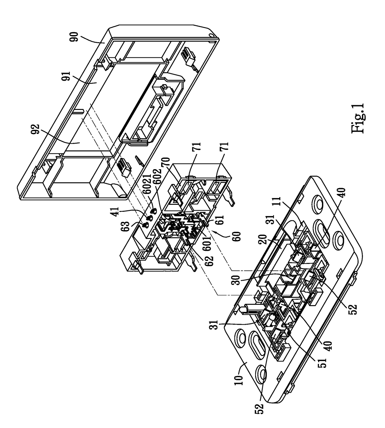
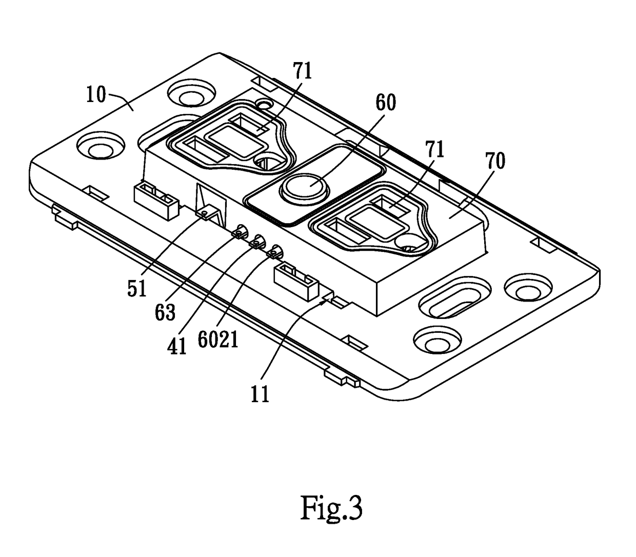
[0019]Referring to the wall-mounted device of the present invention, the device is provided with a base 10. The base 10 is provided in a wall. The base 10 is provided with a concave part 11. The concave part 11 is disposed with an interior live wire circuit 20 and an exterior live wire circuit 30 as shown in FIG. 6 and FIG. 9, wherein the exterior live wire circuit 20 is connected to a live wire provided in the wall in series to receive the AC power transmitted by the power system of the main switch.

[0020]Further, the concave part 11 of the base 10 is not only disposed with the above circuit, but also an earth wire circuit 40 and a neutral wire circuit 50 as shown in FIG. 6 and FIG. 9, wherein the neutral wire circuit 50 is connected to a neutral wire provided in the wall in series to transmit current back to the power of the main switch. The potential is usually equal or close to zero, and the earth wire circuit 40 is connected with, in series, a conductor which has a potential equ...

second embodiment

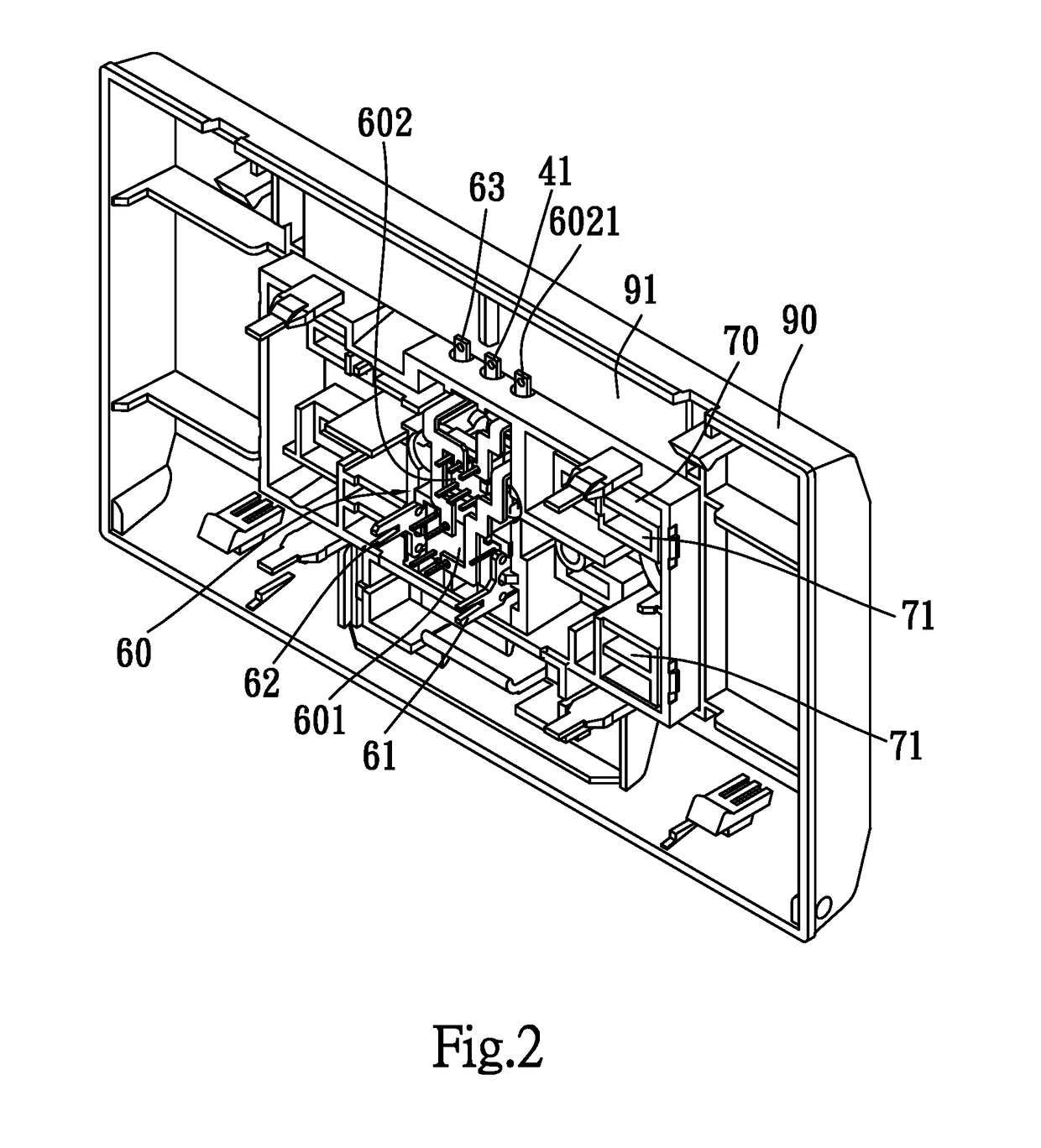
[0029]Furthermore, in the present invention, at least one module circuit board 91 of the cover plate 90 is electrically connected to the exterior live wire circuit 20 of the base 10 to supply power to at least one module circuit board 91. The at least one module circuit board 91 of the cover plate 90 is provided with a transformer (not shown in figures) to transformer power, transmitted by the exterior live wire circuit 20 of the base 10, to needful power. The at least one module circuit board 91 of the cover plate 90 is configured by at least one element selected from a group including a wireless transmission module circuit board, a temperature detection module circuit board, a power measurement module circuit board, a signal control module circuit board, a display module circuit board and an infrared detection module circuit board. The at least one module circuit board 91 as mentioned above is provided with a control chip, not shown in Figures, so as to attain an effect of perform...


PUM


Abstract

Disclosed is a wall-mounted device, which is mainly provided with a base and a cover plate, and the at least one module circuit board is provided in the cover plate. The power terminal of at least one module circuit board is electrically connected to an exterior live wire circuit of the base, so the interior live wire circuit is able to independently supply power to the module circuit board of the cover plate. As the result, the base is able to fit or replace with any cover plate provided with module circuit board, and connects to any electronic device or network to remotely control and operate.

Description

BACKGROUND OF THE INNOVATION PATENT1. Field of the Innovation Patent[0001]The present innovation patent relates to a wall-mounted device, particularly with regard to a design, which is provided with an interior live wire circuit and an exterior live wire circuit, to attain an effect that the exterior live circuit supplies power and detects circuit independently, and is applied to an outlet device mounted in the wall and the like.2. The Related Arts[0002]Nowadays, the electricity consumption has increased year by year and the electricity prices are gradually rising. Therefore, saving energy becomes a crucial issue.[0003]Other than the usage of supplying power to electrical appliances or electrical devices, recently, outlet switches has also been formed a smart outlet that can detect circuit and control circuit, so as to manage electrical appliances or electrical devices or to analyze the electricity consumption of electrical appliances or electrical devices.[0004]However, the convent...

Claims


Application Information

Patent Timeline
IPC IPC(8): H05K5/00H01R13/66H01R13/70H01R25/00H02G3/12H02G3/08H02B1/42H01H47/22G01R15/18G01R21/06G01K13/00
CPCH05K5/0026H01R13/665H01R13/70H01R25/006H02G3/123G01K13/00H02B1/42H01H47/22G01R15/183G01R21/06H02G3/081H02G3/12H02G3/14H02G3/18H01R2103/00H01R13/701H01R13/7175H01R24/78G01K1/08H01H13/02H01H1/5805
Inventor LI, CHAO-HAN
Owner HAN CHUANG INT CO LTD
Why Eureka
Try Eureka