Backlight module

a backlight module and backlight technology, applied in the field of backlight modules, can solve the problems of insufficient or excessive compensation, uneven backlight provided by the backlight module, and the inability to effectively solve the non-uniformity of the back, so as to eliminate or reduce the degree of backlight non-uniformity

Active Publication Date: 2020-06-11
QUISDA CORP
View PDF1 Cites 0 Cited by
  • Summary
  • Abstract
  • Description
  • Claims
  • Application Information

AI Technical Summary

Benefits of technology

[0003]An objective of the invention is to provide a backlight module, of which a light-guiding plate has reflection spots disposed on a fringe portion of

Problems solved by technology

However, the back light provided by the backlight module is usually uneven at the circumference of the light-guiding plate.
However, in practice, it probably induces insufficient or exc

Method used


Image

  • Backlight module
  • Backlight module
  • Backlight module

Examples


Embodiment Construction

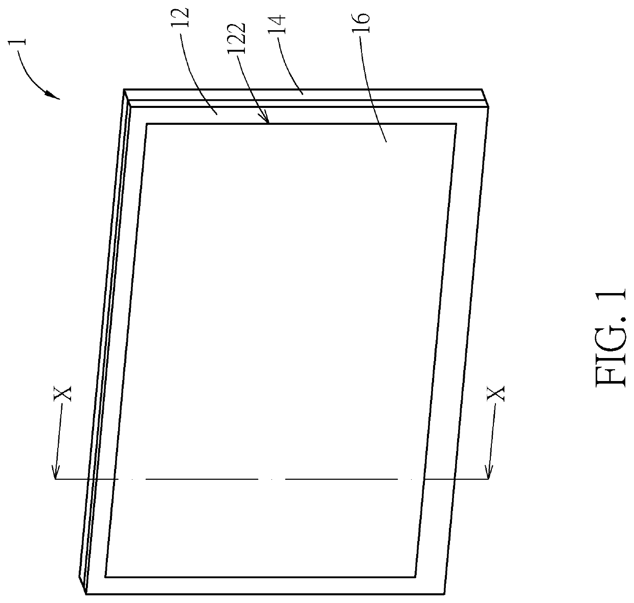
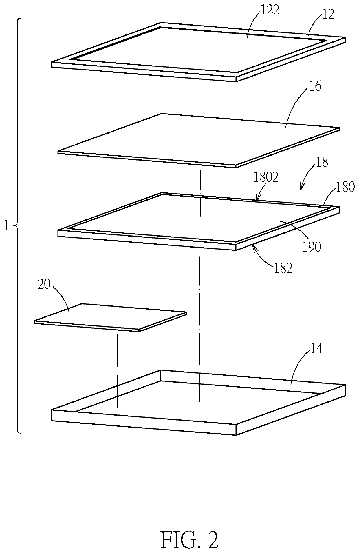
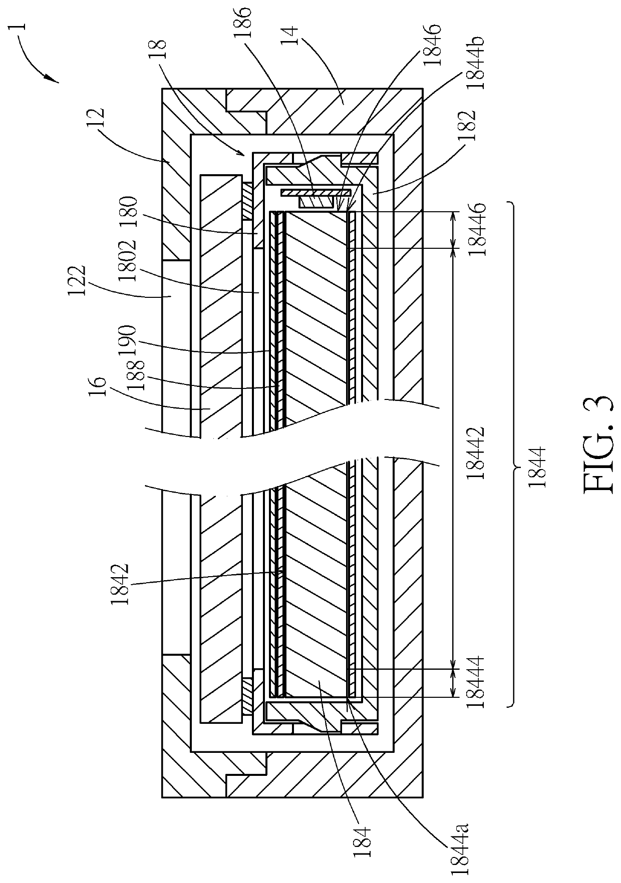
[0015]Please refer to FIG. 1 and FIG. 2. A displaying device 1 according to an embodiment includes a front frame 12, a back cover 14, a liquid crystal panel 16, a backlight module 18, and a control module 20. The front frame 12 and the back cover 14 are engaged with each other to form an accommodating space for accommodating the other components. The front frame 12 has a window 122. The liquid crystal panel 16 is exposed through the window 122. The liquid crystal panel 16 can be realized by a liquid crystal panel of a common liquid crystal display in practice, which will not be described in addition. The backlight module 18 is disposed under the liquid crystal panel 16 for providing back light to the liquid crystal panel 16 to display images. The control module 20 is electrically connected to the liquid crystal panel 16 and the backlight module 18 for controlling the operation of the liquid crystal panel 16 and the backlight module 18. For simplification of the figures, the control ...


PUM


Abstract

A backlight module includes a light-guiding plate, a plurality of reflection spots, and a light source. The reflection spots are disposed on a back surface of the light-guiding plate. Light emitted by the light source enters the light-guiding plate through a light input side surface of the light-guiding plate, and is reflected by the reflection spots to emit out of the light-guiding plate through a light output surface of the light-guiding plate. The back surface includes a central portion and a fringe portion. The fringe portion extends along an edge of the back surface. The distribution density of the reflection spots on the fringe portion gradually decreases in a direction from the central portion toward the fringe portion.

Description

BACKGROUND OF THE INVENTION1. Field of the Invention[0001]The present invention relates to a backlight module, and more particularly to a backlight module with a light-guiding plate.2. Description of the Prior Art[0002]Many backlight modules use a light-guiding plate for guiding light to provide flat back light for but not limited to a liquid crystal panel. However, the back light provided by the backlight module is usually uneven at the circumference of the light-guiding plate. If the backlight module uses a quantum dot film, the light emitted out from the circumference of the backlight module is bluer or yellower, which influences image displaying of the liquid crystal panel. For this case, some backlight modules may be processed with compensation printing at portions of the reflector sheet of the backlight modules corresponding to the circumference of the light-guiding plate of the backlight modules. However, in practice, it probably induces insufficient or excessive compensation...

Claims


Application Information

Patent Timeline
IPC IPC(8): G02F1/1335F21V8/00
CPCG02F1/133605G02B6/0018G02B6/0043G02B6/0061
Inventor CHANG, WEI-JUNGCHEN, HSIAO-YUN
Owner QUISDA CORP
Why Eureka
Try Eureka