Imaging lens

a technology of imaging lens and aperture, applied in the field of imaging lens, can solve the problems of difficult downsizing of imaging lens, inconvenient mounting in small-sized cameras, etc., and achieve the effects of satisfactory aberration correction, small size, and high resolution

a technology of imaging lens and aperture, applied in the field of imaging lens, can solve the problems of difficult downsizing of imaging lens, inconvenient mounting in small-sized cameras, etc., and achieve the effects of satisfactory aberration correction, small size, and high resolution

US20200271898A1Pending Publication Date: 2020-08-27TOKYO VISIONARY OPTICS CO LTD

Image

  • Imaging lens
  • Imaging lens
  • Imaging lens

Examples


Embodiment Construction

bed.

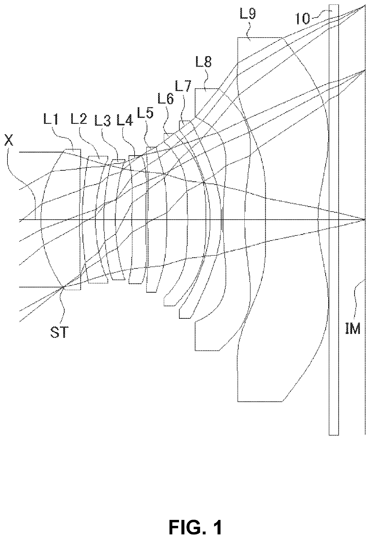
[0113]FIGS. 1, 4, 7, 10, 13, 16, 19, 22, 25 and 28 are schematic sectional views of the imaging lenses in Numerical Data Examples 1 to 10 according to the embodiment, respectively. Since the imaging lenses in those Numerical Data Examples have the same basic configuration, the lens configuration of the embodiment will be described with reference to the sectional view of Numerical Data Example 1.

[0114]As shown in FIG. 1, the imaging lens of the embodiment includes a first lens L1 having positive refractive power; a second lens L2 having negative refractive power; a third lens L3 having negative refractive power; a fourth lens L4 having negative refractive power; a fifth lens L5; a sixth lens L6; a seventh lens L7; an eighth lens L8; and a ninth lens having negative refractive power, arranged in the order from an object side to an image plane side. In addition, between the ninth lens L9 and an image plane IM of an imaging element, there is provided a filter 10. Here, the filter 10...


PUM


Abstract

An imaging lens includes a first lens having positive refractive power; a second lens having negative refractive power; a third lens having negative refractive power; a fourth lens having negative refractive power; a fifth lens; a sixth lens; a seventh lens; an eighth lens; and a ninth lens having negative refractive power, arranged in this order from an object side to an image plane side. The ninth lens is formed in a shape so that a surface thereof on the image plane side has an aspherical shape having an inflection point.

Description

BACKGROUND OF THE INVENTION AND RELATED ART STATEMENT[0001]The present invention relates to an imaging lens for forming an image of an object on an imaging element such as a CCD sensor and a CMOS sensor. In particular, the present invention relates to an imaging lens suitable for mounting in a relatively small camera such as a camera to be built in a portable device, e.g., a cellular phone and a portable information terminal, a digital still camera, a security camera, an onboard camera, and a network camera.[0002]In case of a lens configuration comprised of nine lenses, since the number of lenses that composes the imaging lens is many, it has higher flexibility in designing and can satisfactorily correct aberrations. For example, as the conventional imaging lens having a nine-lens configuration, an imaging lens described in Patent Reference has been known.[0003]Patent Reference: Japanese Patent Application Publication No. 2018-156011[0004]According to the conventional imaging lens o...

Claims


Application Information

Patent Timeline
27 Aug 2020
Publication
US20200271898A1
IPC
G02B9/64; G02B13/00; G02B15/14
CPC
G02B9/64; G02B13/002; G02B13/005; G02B15/14; G02B13/0045; G02B13/18; G02B13/06; G03B30/00
Inventors
HIRANO, HITOSHI