

System and method for lead extraction
a lead extraction and lead technology, applied in the field of system and method for removing implanted lead, can solve problems such as vibration disturbance of tissue application
- Summary
- Abstract
- Description
- Claims
- Application Information
AI Technical Summary
Benefits of technology
Problems solved by technology
Method used
Image

Examples
Embodiment Construction
[0027]In the detailed description, numerous specific details are set forth in order to provide a thorough understanding of the disclosure. However, it will be understood by those skilled in the art that these are specific embodiments and that the present disclosure may be practiced also in different ways that embody the characterizing features of the disclosure as described and claimed herein. In the drawings and descriptions set forth, identical reference numerals indicate those components that are common to different embodiments or configurations.
[0028]The present disclosure will be more fully understood from the following detailed description of the preferred embodiments thereof, taken together with the drawings.
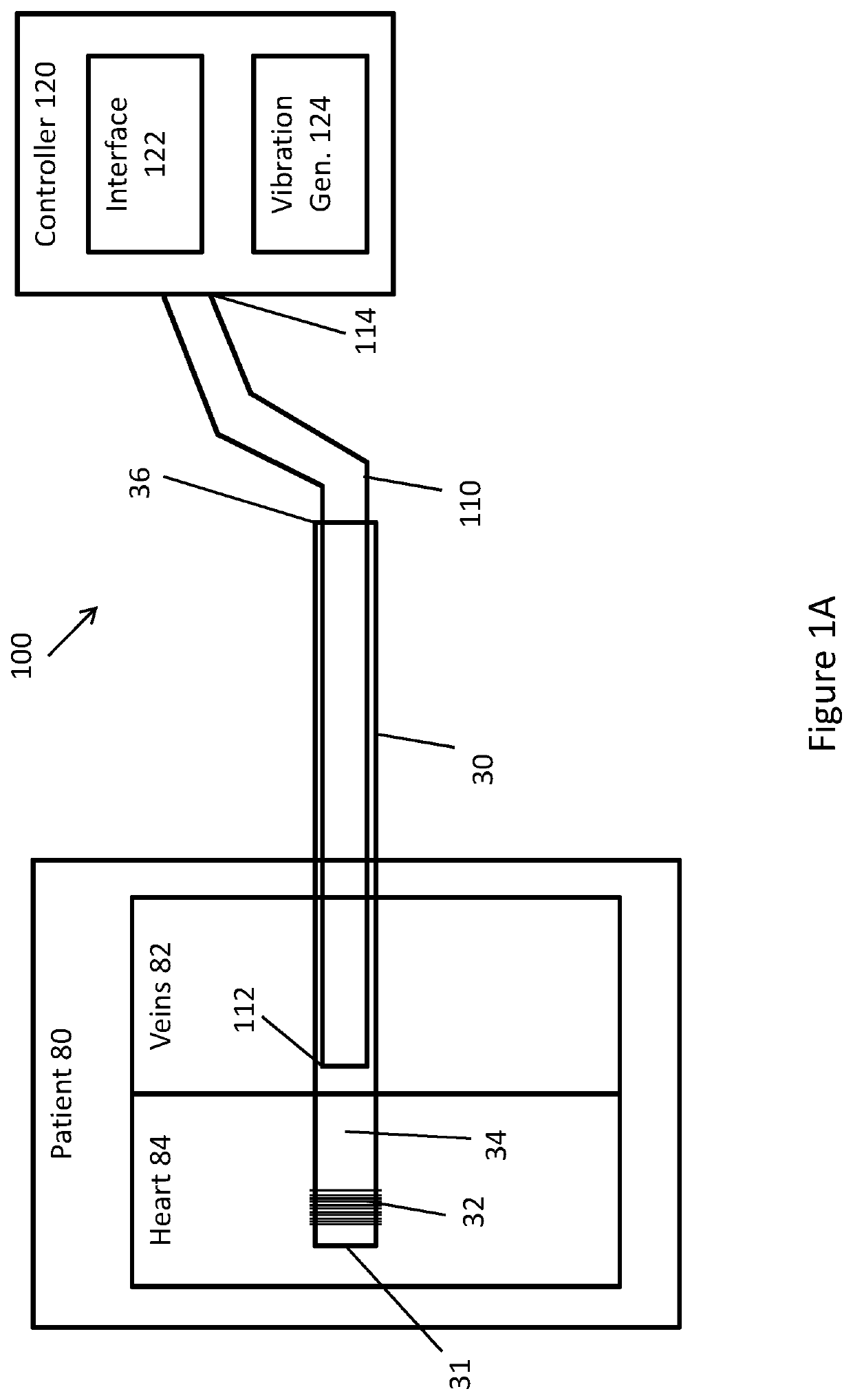
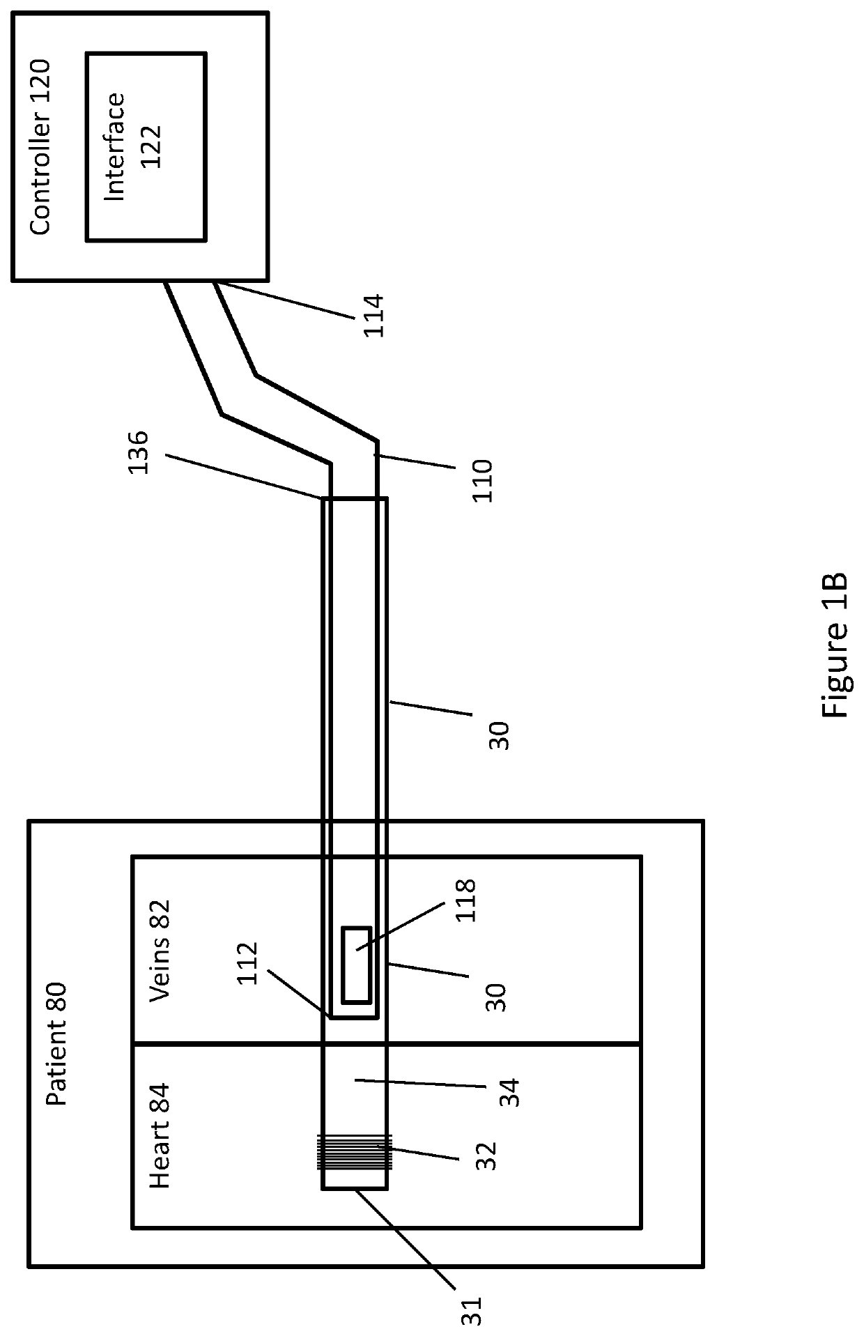
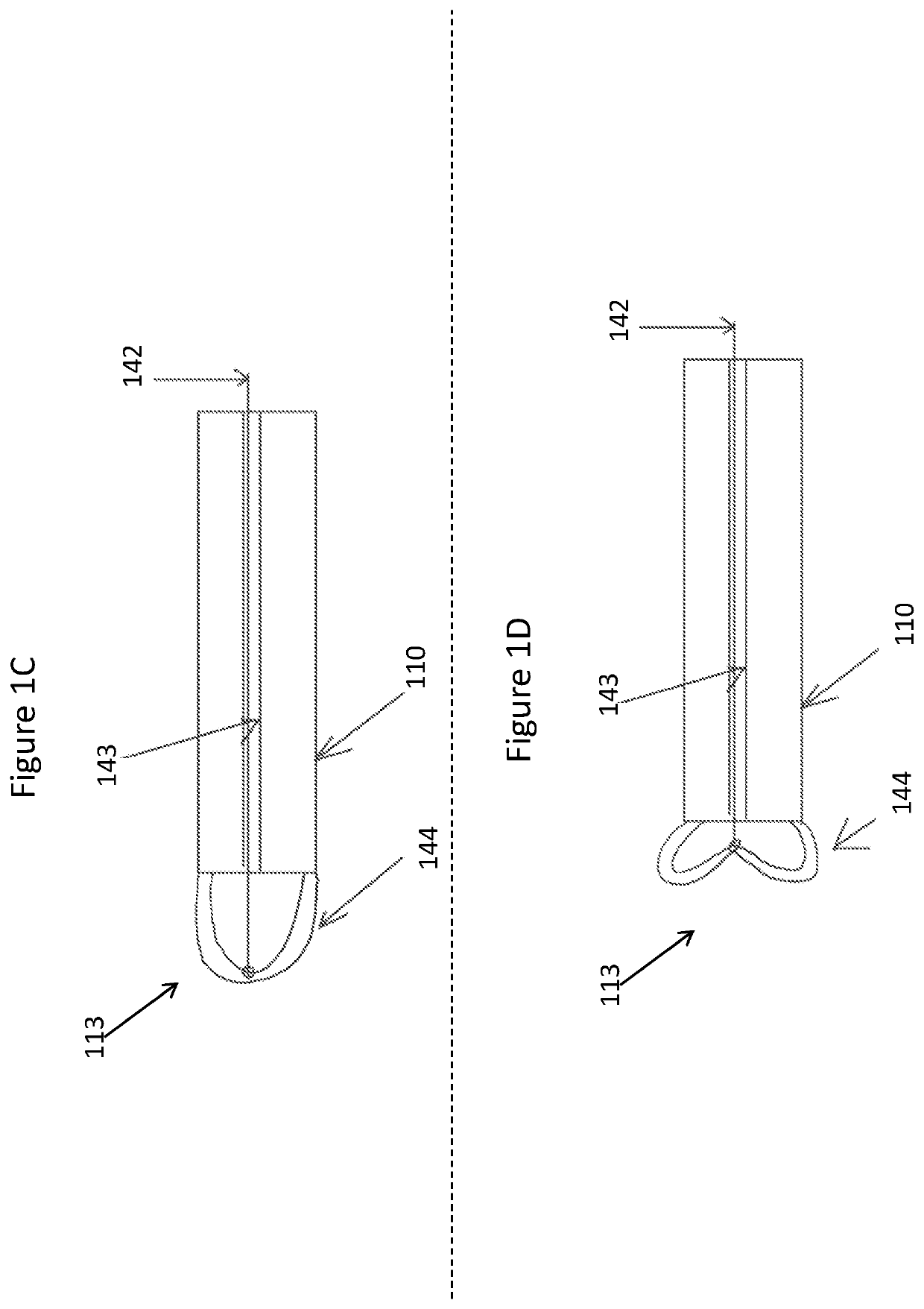
[0029]Reference is now made to FIGS. 1A-1D which are schematic system diagrams showing a system for lead removal according to some embodiments of the present disclosure. As shown in FIGS. 1A and 1B, a cardiac lead 30 has been implanted into a patient 80. Lead 30 passes th...
PUM
 Abstract
Description
Claims
Application Information