Branch apparatus for pipe and a branch method using the same

a branch method and pipe technology, applied in mechanical equipment, branching pipes, transportation and packaging, etc., can solve the problems of complex structure of gas pipes, easy damage to branch pipes 3 and 3, and achieve the effects of small load, easy exposure to the outside, and low vibration

Inactive Publication Date: 2000-05-30
LEE WOO KAG
View PDF3 Cites 13 Cited by
  • Summary
  • Abstract
  • Description
  • Claims
  • Application Information

AI Technical Summary

Benefits of technology

It is an object of the present invention to provide a branch apparatus for a pipe and a branch method using the same which make a laying depth of the main pipe be identical with that of the branch pipe by horizontally installing a branch appar

Problems solved by technology

Accordingly, there are many gas pipes for supplying each home and building with LNG under the ground of all cities and villages, and the gas pipes are complexly laid like cobwebs.
Since the branch pipe 3 is positioned at a position higher than the main pipe 2, the branch pipe 3 receives a large load and vibrati

Method used


Image

  • Branch apparatus for pipe and a branch method using the same
  • Branch apparatus for pipe and a branch method using the same
  • Branch apparatus for pipe and a branch method using the same

Examples


Embodiment Construction

Reference will now be made in detail to the preferred embodiment of the present invention, examples of which are illustrated in the accompanying drawings.

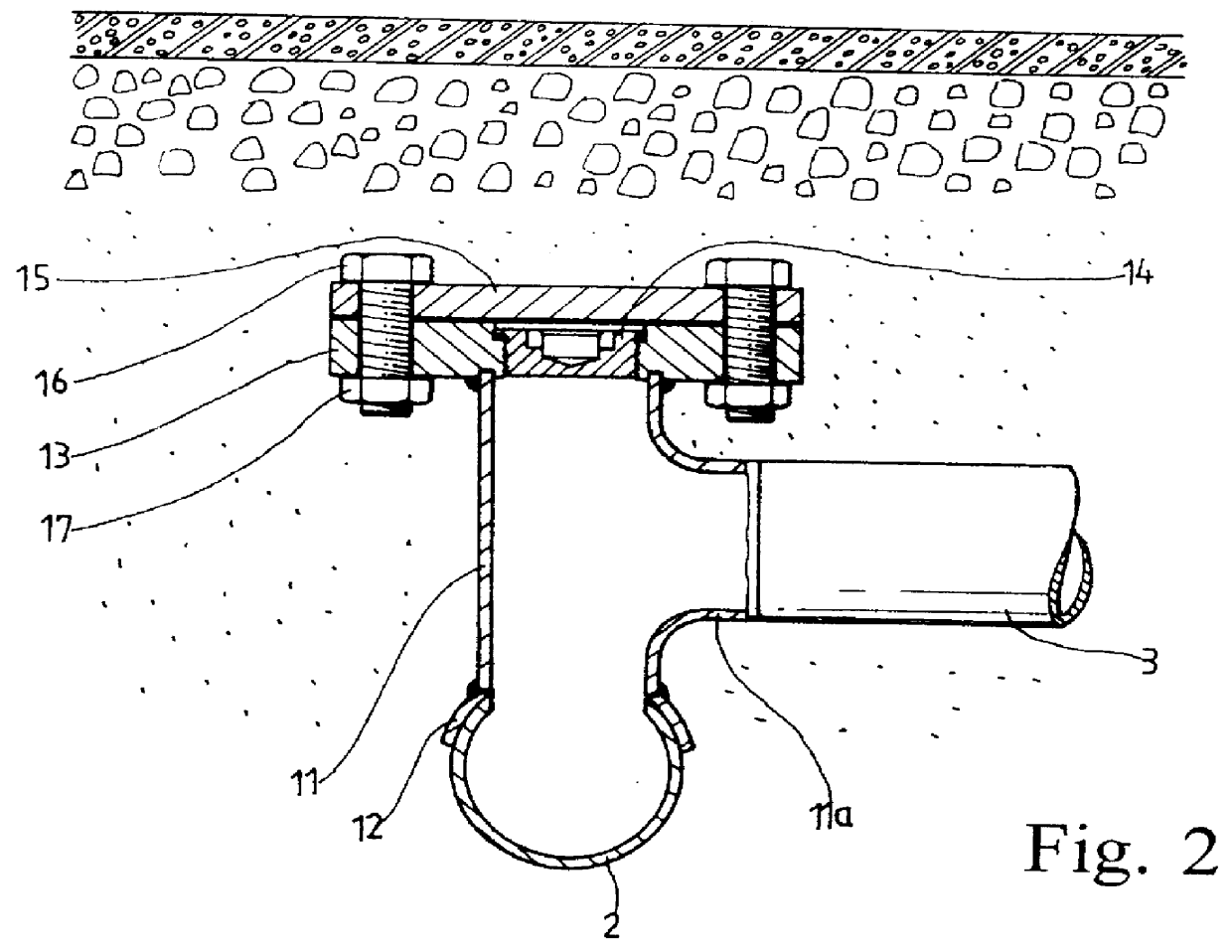
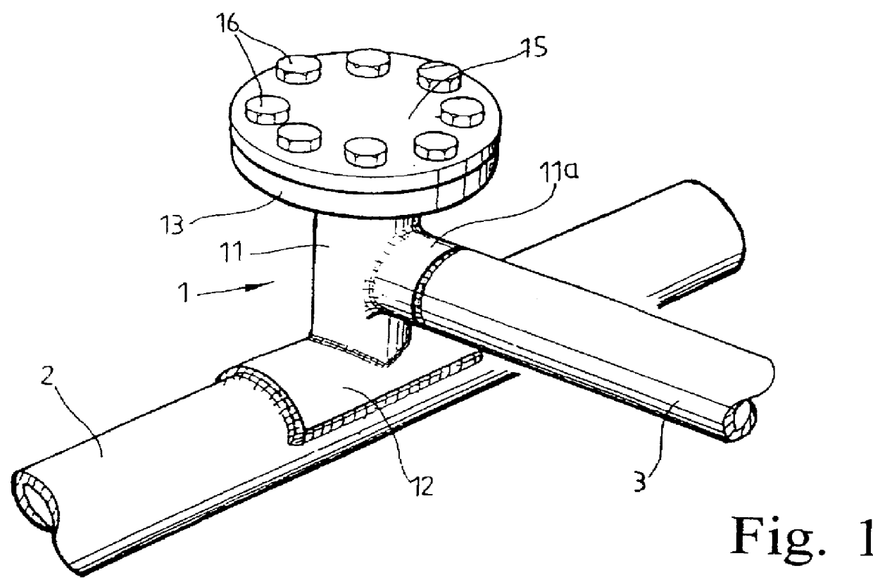
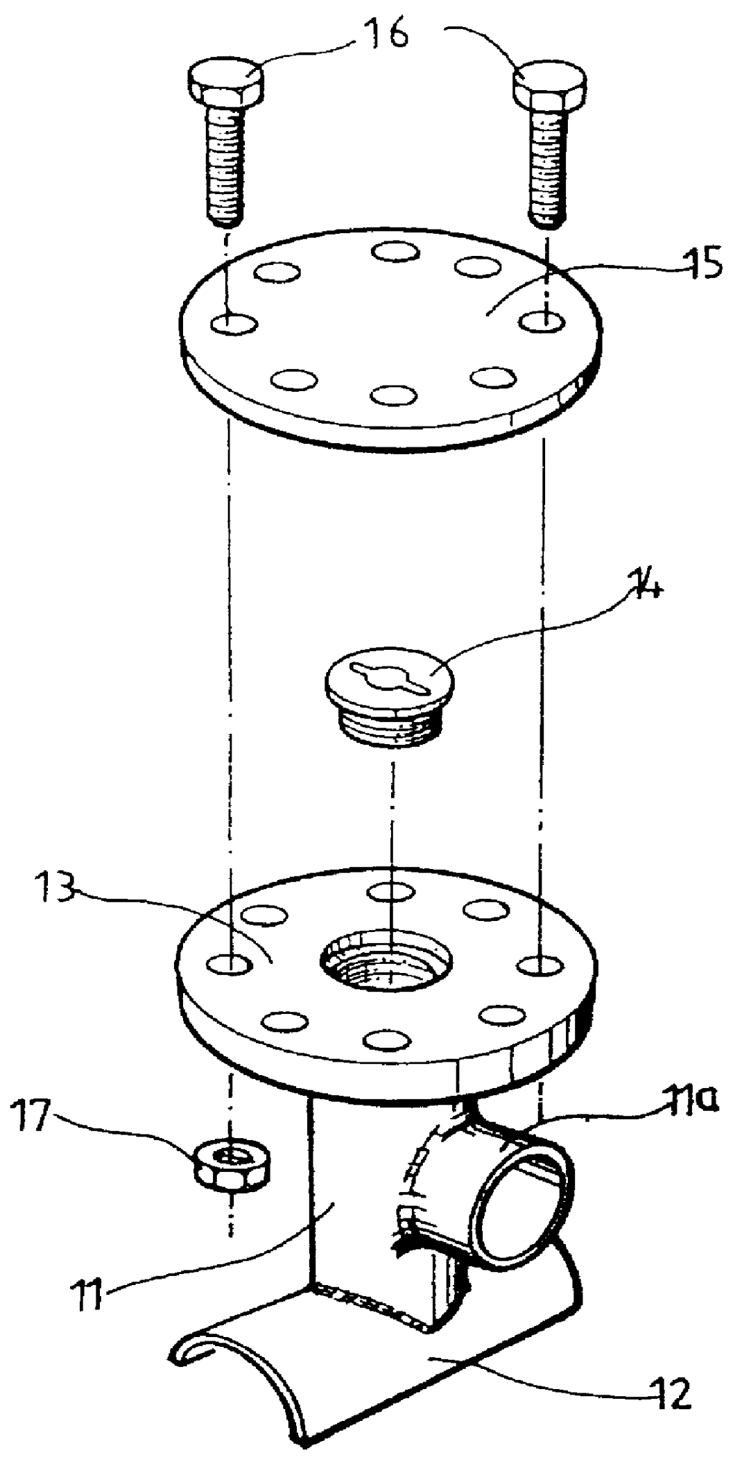
FIG. 7 is a cross-sectional view illustrating a coupling state of a branch apparatus in accordance with a preferred embodiment of the present invention; and FIG. 8 is a cross-sectional view illustrating that a main pipe is pierced by the branch apparatus in accordance with a preferred embodiment of the present invention.

As shown in FIGS. 7 and 8, a branch apparatus in accordance with a preferred embodiment of the present invention includes a T-type pipe 20 having a horizontal pipe 20a whose both ends are opened and a vertical pipe 20b connected to an upper part of a center of the horizontal pipe 20a; a reinforcement plate 21 welded to a main pipe 2, for being welded to one end of the horizontal pipe 20a of the T-type pipe 20; a flange 22 which is welded to an upper end of the vertical pipe 20b of the T-type pipe 20, and has female ...


PUM


Abstract

A branch apparatus for a pipe and a branch method using the same connect a branch pipe installed to a place requiring a fluid such as a gas, a chemical substance and water to a main pipe through which the fluid flows. The branch apparatus for a pipe and the branch method using the same make a laying depth of the main pipe be identical with that of the branch pipe by horizontally installing a branch apparatus, and thus make the branch pipe receive both a low vibration and a small load from the ground. The branch apparatus includes a T-type pipe having a horizontal pipe whose both ends are opened and a vertical pipe connected to an upper part of a center of the horizontal pipe; a reinforcement plate welded to the main pipe for being welded to one end of the horizontal pipe of the T-type pipe; a flange which is welded to an upper part of the vertical pipe of the T-type pipe, and has female screw lines in a center thereof; and a plug coupled with the center of the flange.

Description

1. BACKGROUND OF THE INVENTION1. Field of the InventionThe present invention relates generally to a branch apparatus for a pipe and a branch method using the same which connect a branch pipe installed to a place requiring a such as a gas, a chemical substance and water to a main pipe through which the fluid flows. More particularly, it relates to a branch apparatus for a pipe and a branch method using the same which make a laying depth of the main pipe be identical with that of the branch pipe by horizontally installing a branch apparatus, and thus make the branch pipe receive a low vibration and a small load from the ground.2. Description of the Related ArtIn recent years, most homes use a liquefied natural gas (LNG) as a household fuel, and buildings and houses mostly use the LNG as a fuel of a heating device. Accordingly, there are many gas pipes for supplying each home and building with LNG under the ground of all cities and villages, and the gas pipes are complexly laid like co...

Claims


Application Information

Patent Timeline
IPC IPC(8): F16L41/04F16L41/00
CPCF16L41/04Y10T137/612Y10T137/6123
Inventor LEE, WOO KAG
Owner LEE WOO KAG
Why Eureka
Try Eureka