Latching hinged cover

a hinged cover and hinge technology, applied in the field of hinge assembly, can solve the problems of requiring the use of tools or considerable manual effort, affecting the reattachment operation, and exposing the main cabinet section, so as to facilitate the reattachment of the cover, the effect of quick and easy manner

Inactive Publication Date: 2000-06-06
ECE TELECOM LTD
View PDF10 Cites 23 Cited by
  • Summary
  • Abstract
  • Description
  • Claims
  • Application Information

AI Technical Summary

Benefits of technology

An object of the present invention is to provide a hinge assembly for pivotally mounting a pivotal member to a body member, which hinge assembly is particularly useful for cabinet structures to facilitate the reattachment of the cover to a main cabinet section in a quick and easy manner and without the need for tools or special manual effort. Another object of the present invention is to provide a cabinet including one or more such hinge assemblies for mounting a cover section to the main cabinet section in a manner which permits the cover section to be conveniently attached from and reattached to the main cabinet section without the need for tools or special manual effort.
According to still further features in the described preferred embodiment, the socket of the second part is in the form of a socket ring having a central opening for pivotally receiving the hinge pin of the first part. More particularly, the first part includes a first section telescopingly receiving the hinge pin, and a second section spaced below and aligned with the hinge pin of the first section to define a transverse slot between the first and second sections extending transversely of the hinge pin for receiving the socket ring of the second part when pivotally mounted to the first part. In addition, the outer tip of the hinge pin is tapered, and the edge of the socket ring facing the hinge pin, when the socket ring is to inserted into the transfirst slot, is also tapered, to facilitate the entry of the socket ring into the slot when pivotally mounting the first part to the second part.
FIG. 1 is a side view illustrating a main cabinet section and cover section carrying the respective parts of one form of hinge assembly constructed in accordance with the present invention to enable the cover section to be either pivotally mounted to, or detached from the main cabinet section in a convenient and quick manner; and without the need for tools or special manual effort.

Problems solved by technology

Both the removal operation and the re-attachment operation require the use of tools or considerable manual effort.
While the need for tools, or such manual effort, to detach the cover from the main cabinet section generally would not deter the servicing personnel from detaching the cover in order to facilitate access to the components in the cabinet for servicing purposes, the need for such tools and / or manual effort, and the time require to re-apply the cover, do frequently deter the servicing personnel from re-attaching the cover to the main cabinet section, thereby leaving the main cabinet section uncovered.
Failure to re-attach the cover section to the main cabinet section could create a hazardous situation with respect to the electrical components within the main cabinet section.
Moreover, it could lead to the loss or misplacement of the cover when it is desired to reattach it to the main cabinet section.

Method used


Image

  • Latching hinged cover
  • Latching hinged cover
  • Latching hinged cover

Examples


Embodiment Construction

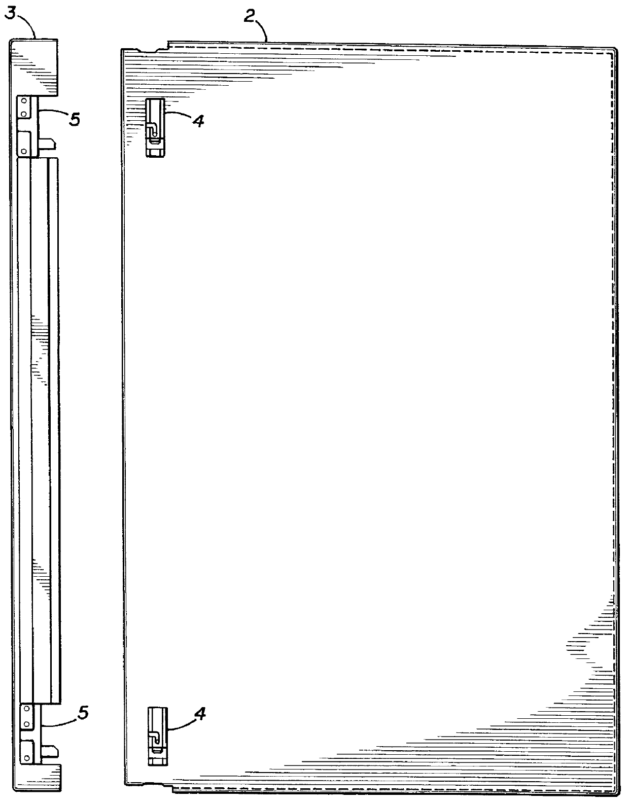
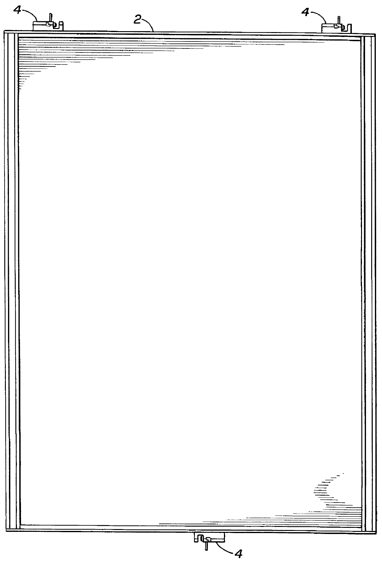
With reference to FIG. 1, there is illustrated a cabinet constituted of a main cabinet section 2 and a cover section 3, which may be either pivotally mounted to the main cabinet section 2, or detached from it, in a quick and convenient manner without the need for tools or screws, bolts or other fastening elements. For this purpose, a hinge assembly is used constructed in accordance with the present invention, as described particularly below, which hinge assembly includes a first part, generally designated 4, secured to the main cabinet section 2, and a second part, generally designated 5, which is secured to the cover section 3. In the example illustrated in FIGS. 1 and 2, the cabinet includes three such hinge assembles, two located at the ends of one edge of the cabinet, and a third located centrally of the opposite edge, as shown particularly in FIG. 2. In such an arrangement, the two hinge assemblies serve to pivotally mount the cover section 3 to the main cabinet section 2, and ...


PUM


Abstract

A hinge assembly, which permits convenient assembly and disassembly by simple push operations, includes a first part to be secured to a body member and carrying a hinge pin, and a second part to be secured to a pivotal member and carrying a socket for pivotally receiving the hinge pin of the first part. The hinge pin is retractably mounted to the first part so as to be movable to an extended, operative position receivable within the socket of the second part for pivotally mounting the pivotal member to the base member, and to a retracted, released position spaced from the socket of the second part for permitting removal of the pivotal member from the body member. Also described is a cabinet with at least one such hinge assembly on each of the two opposite edges of the main cabinet section and cover section, respectively. One hinge assembly serves as a pivotal mounting of the cover section to the main cabinet section permitting the cover section to be pivoted to its open and closed positions with respect to the main cabinet section; and the other hinge assembly serves as a releasable latch for latching the cover section in its closed position with respect to the main cabinet section.

Description

FIELD AND BACKGROUND OF THE INVENTIONThe present invention relates to hinge assemblies for pivotally mounting a pivotal member to a base member. The invention is particularly useful in cabinet structures for pivotally mounting a cover to the main cabinet section, and the invention is therefore described below with respect to this application.Cabinets including a cover or panel pivotally mounted to a main cabinet section are widely used, among many other applications, in the electronics industry for housing the electronic components in a compact and readily-accessible manner for servicing purposes. Frequently, the cover is removed from the cabinet section to provide more convenient access to the components within the cabinet than would be allowed by the pivotal mounting. In the conventional cabinet structures now in use, the hinge assemblies pivotally mounting the cover to the main cabinet section are generally secured by screws or bolts, which must be removed for removing the cover ...

Claims


Application Information

Patent Timeline
Patent Type & Authority Patents(United States)
IPC IPC(8): E05D7/10E05D7/00
CPCE05D7/1011E05D7/1077Y10T16/53605Y10T16/557Y10T16/527
Inventor SCHREIBER, JACOB
Owner ECE TELECOM LTD
Why Eureka
Try Eureka