Plasma display panel with spacers diagonally opposed to the electrode sets

Inactive Publication Date: 2001-08-21
LG ELECTRONICS INC
View PDF4 Cites 14 Cited by
  • Summary
  • Abstract
  • Description
  • Claims
  • Application Information

AI Technical Summary

Problems solved by technology

However, this may bring about crosstalk, undesirable discharge, between the cells.
Thus, if there is a gap between the barrier and upper substrate, plas

Method used


Image

  • Plasma display panel with spacers diagonally opposed to the electrode sets
  • Plasma display panel with spacers diagonally opposed to the electrode sets
  • Plasma display panel with spacers diagonally opposed to the electrode sets

Examples


Embodiment Construction

Reference will now be made in detail to the preferred embodiments of the present invention, examples of which are illustrated in the accompanying drawings. Wherever possible, the same reference numbers will be used throughout the drawings to refer to the same or like parts.

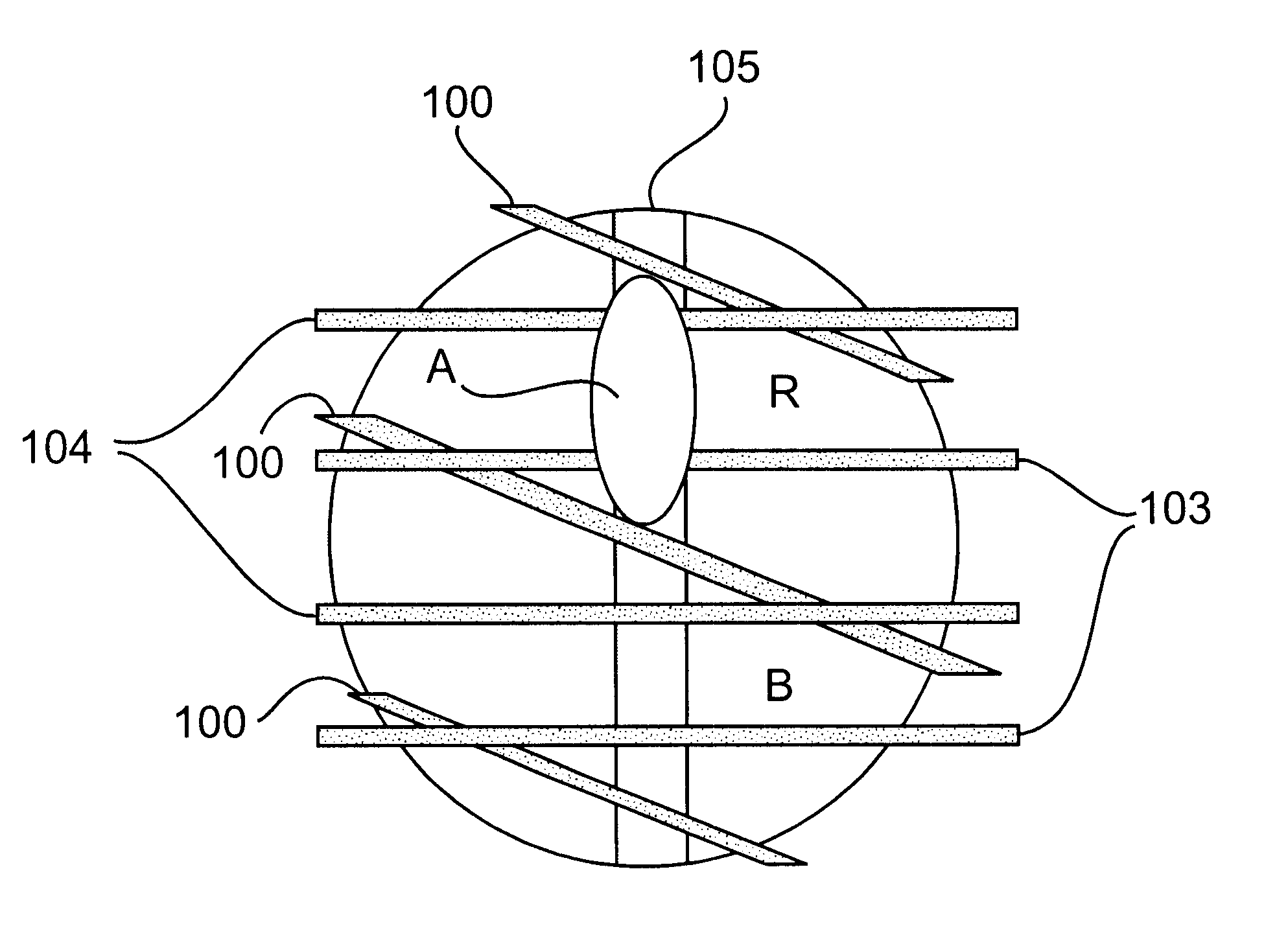
A PDP consistent with the present invention provides a data electrode and barrier that are not arranged in parallel with each other but they are located at an angle to each other. The PDP also may have the barrier formed on an upper substrate to prevent discharging due to plasma diffusion between cells.

A PDP of the present invention is explained below with reference to FIGS. 3 to 7. Referring to FIG. 4, the PDP of the present invention is constructed in such a manner that a sustain electrode 103, scan electrode 104 and data electrode 105 are arranged between upper and lower substrates 101 and 102, sustain electrode 103 and scan electrode 104 being located in parallel with each other, data electrode 105 is located ...


PUM


Abstract

A plasma display panel is provided to solve the problem of crosstalk due to discharge which generates from plasma diffusion between cells adjacent to each other, preventing color spread of the vertical edge. The plasma display panel of the invention includes a barrier located at an angle to its data electrode, the barrier being formed on an upper substrate on which a sustain electrode is formed.

Description

A. Field of the InventionThe present invention relates to a plasma display panel (PDP), more particularly to a three-electrode PDP.B. Description of the Prior ArtThe unit cell of a conventional three-electrode surface discharging PDP is constructed, as shown in FIG. 1, in such a manner that a scan electrode 2 to which a scan pulse is applied during address period and a sustain electrode 3 to which a sustain pulse for maintaining discharge are formed on an upper substrate 10, a data electrode 1 to which a data pulse for generating sustain discharge between scan electrode 2 and sustain electrode 3 is formed on a lower substrate 20, a dielectric layer 6 is coated under upper substrate 10 for protecting scan electrode 2 and sustain electrode 3, and an R, G, B phosphor 5 is formed on data electrode 1 and placed between barriers 4 supporting upper and lower substrates 10 and 20. A cell (not shown) is formed at a portion where a vertical electrode (that is, scan electrode 2 and sustain ele...

Claims


Application Information

Patent Timeline
IPC IPC(8): H01J17/16H01J17/02H01J17/49G09F9/30G09F9/313H01J11/12H01J11/22H01J11/24H01J11/26H01J11/34H01J11/36H01J11/42H01J17/04
CPCH01J11/12H01J11/36H01J2211/365H01J11/32
Inventor HONG, JIN-WON
Owner LG ELECTRONICS INC
Why Eureka
Try Eureka