Free-wheeling door lock mechanism

a free-wheeling door lock and mechanism technology, applied in the direction of mechanical control devices, keyhole guards, restricting/preventing/returning movement of parts, etc., can solve the problem of high cost of free-wheeling door locks previously developed, and achieve the effect of low cos

Inactive Publication Date: 2002-03-19
SCOVILL LOCK S A DE
View PDF19 Cites 57 Cited by
  • Summary
  • Abstract
  • Description
  • Claims
  • Application Information

AI Technical Summary

Benefits of technology

The cam slot has a longitudinal portion and a circumferential portion and the cam is axially slidable relative to the spindle from an unlocked position to a locked position. In the unlocked position the finger projects inwardly from the spindle into the longitudinal portion of the cam slot to couple the spindle to the cam. In this position rotation of the spindle rotates the cam to open the door. In the locked position the finger projects inwardly from the spindle into the circumferential portion of the cam slot. In this position the spindle will free-wheel relative to the cam and rotation of the spindle will not open the door. This design allows the lever handle to be directly and non-rotatably connected to the spindle in the usual manner of lock mechanism that do not free-wheel, while still providing free-wheeling performance. This arrangement provides for a lower cost device.

Problems solved by technology

This problem is particularly acute for cylindrical locks which have less internal room than mortise type locks to accommodate heavy duty locking components.
Free-wheeling door locks which have previously been developed have been expensive due to the large number of parts, the multiple manufacturing steps needed to make the parts and the difficulty of assembly of the lock at the factory.

Method used


Image

  • Free-wheeling door lock mechanism
  • Free-wheeling door lock mechanism
  • Free-wheeling door lock mechanism

Examples


Embodiment Construction

)

In describing the preferred embodiment of the present invention, reference will be made herein to FIGS. 1-6 of the drawings in which like numerals refer to like features of the invention.

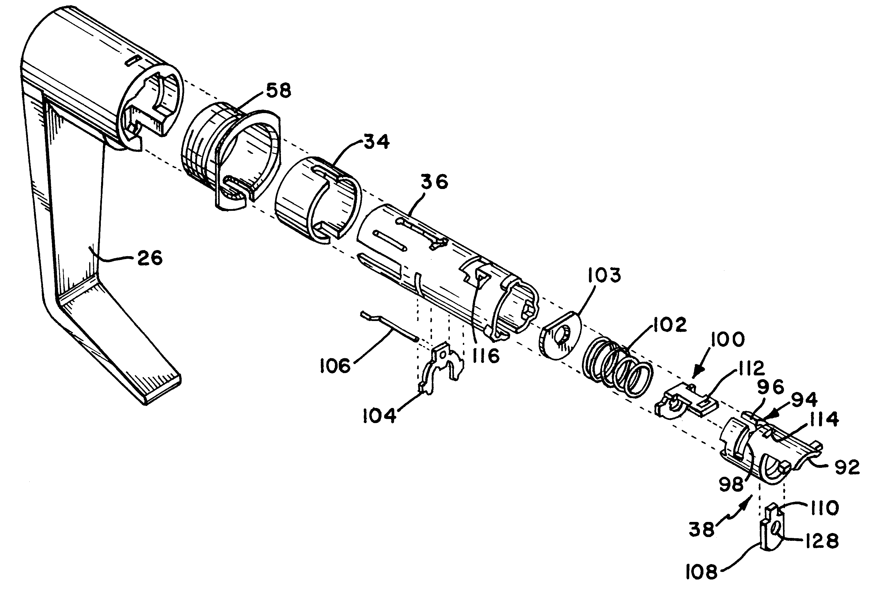
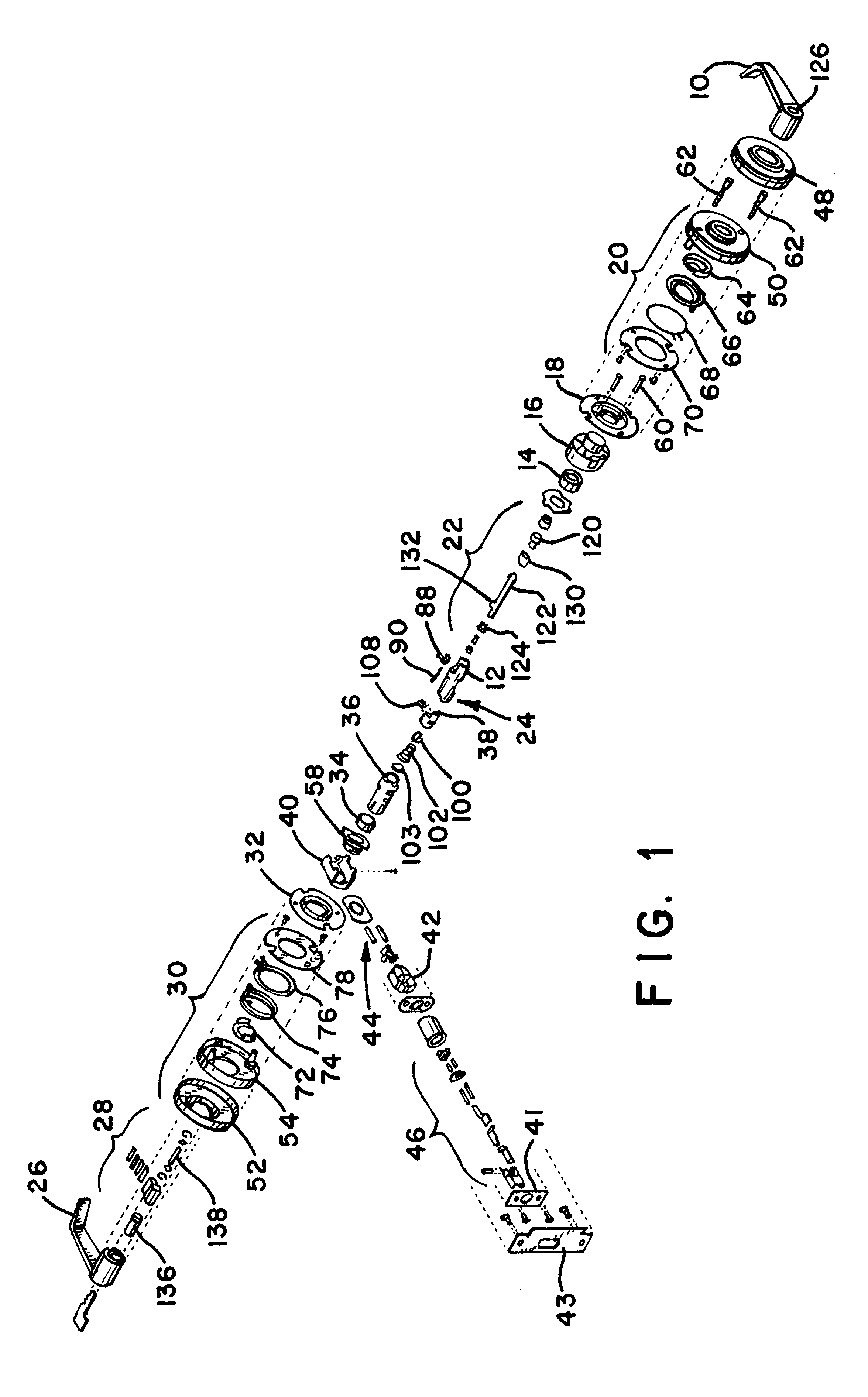
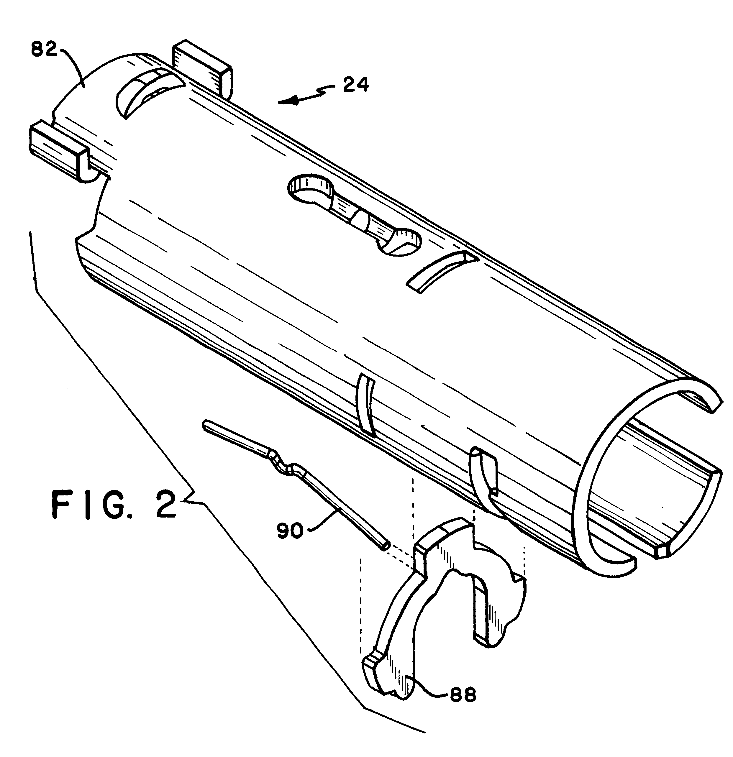
FIG. 1 provides an exploded view of a free-wheeling lock incorporating a free-wheeling lock mechanism according to the present invention. The free-wheeling lock mechanism described generally includes an inner side and an outer side. The inner side includes those components that are on the inside of the door being locked, i.e., in the secure area, and the outer side includes those components that are on the outer side of the door, i.e., in the public area. Referring to FIGS. 1 and 2, the inner side of the free-wheeling lock includes an inner lever handle 10 connected to an inner spindle 12. The connection between the inner lever handle 10 and the inner spindle 12 is direct and rigid such that there is no relative motion between these two components, and any rotation of the inner handle rotates the i...


PUM


Abstract

A free-wheeling lock mechanism for a cylindrical door lock includes inner and outer spindles directly and non-rotatably connected to corresponding inner and outer lever handles. A latch retractor is located between the spindles and a cylindrical outer cam is located within the outer spindle. The outer cam can slide axially in the outer spindle and includes an approximately T-shaped cam slot having longitudinal and circumferential portions forming the T-shape. A cam scoop is located on the perimeter of the outer cam which extends into the latch retractor and operates the latch retractor to open the door when the outer cam is rotated. The outer spindle has an inwardly projecting finger that cooperates with the cam slot to unlock and lock the mechanism as the outer cam slides axially to align the finger with the longitudinal or circumferential portions of the cam slot. In the unlocked position the finger projects into the longitudinal portion of the cam slot so that rotation of the lever handle turns the outer cam and opens the door. In the locked position the finger projects into the circumferential portion of the cam slot so that the finger does not engage the outer cam and rotation of the lever handle does not open the door.

Description

1. Field of the InventionThe present invention relates to the locking mechanism in door locks of the type which allow the handle to "free-wheel", i.e., rotate without retracting the latch bolt, when the mechanism is locked.2. Description of Related ArtDoors are much easier to open when the door handle is shaped as a lever handle rather than a conventional door knob. For this reason, lever handles are preferred in some applications, and they may be required under applicable regulations for certain doors in public buildings to facilitate access by the disabled and the elderly.However, the lever shape of the door handle allows much greater force to be applied to the internal locking mechanism of the door than can be applied with a round door knob. In most door locks, the locking mechanism prevents the door knob from turning when the door is locked. When a round door knob is replaced by a lever handle, the greater leverage available from such a handle may allow a vandal or thief to brea...

Claims


Application Information

Patent Timeline
Patent Type & Authority Patents(United States)
IPC IPC(8): E05B13/00E05B13/10E05B55/00
CPCE05B55/005E05B13/101E05C9/1808Y10T70/5416Y10T70/5496Y10T70/5832Y10T292/57
Inventor VAZQUEZ, CESAR
Owner SCOVILL LOCK S A DE
Why Eureka
Try Eureka