Wiring harness bending mechanism

a technology of bending mechanism and wiring harness, which is applied in the direction of insulating conductors, cables, and relatively moving parts, etc., can solve the problems of high parts cost, troublesome arrangement work of the above structures, and poor protection of wiring harnesses

Inactive Publication Date: 2002-07-09
YAZAKI CORP
View PDF5 Cites 29 Cited by
  • Summary
  • Abstract
  • Description
  • Claims
  • Application Information

AI Technical Summary

Problems solved by technology

Therefore, the wiring harness could be exposed with poor protection.
Furthermore, arrangement work of the above structures is troublesome and the parts cost is high.

Method used


Image

  • Wiring harness bending mechanism
  • Wiring harness bending mechanism
  • Wiring harness bending mechanism

Examples


Embodiment Construction

)

An embodiment of the present invention will be now described in further detail with reference to the accompanying drawings.

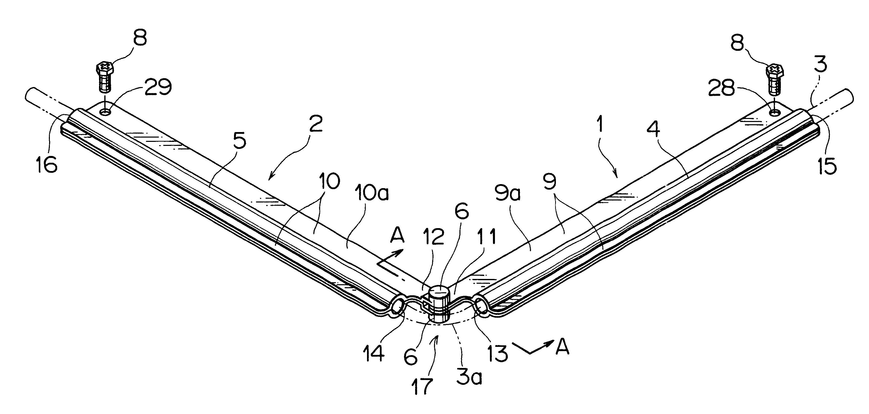
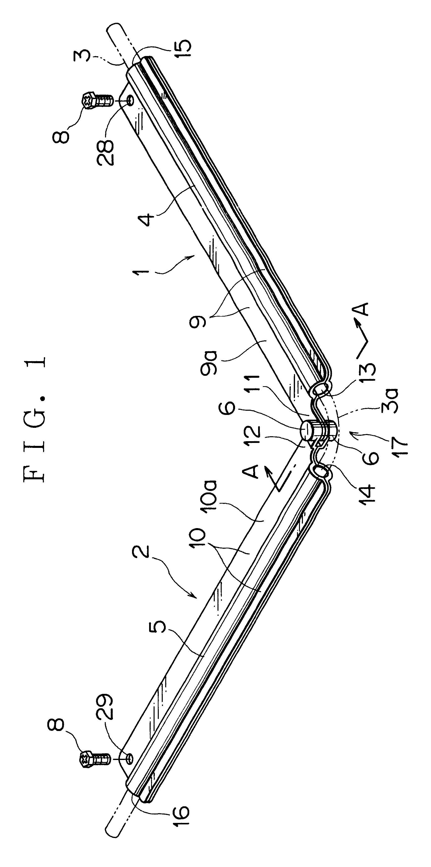
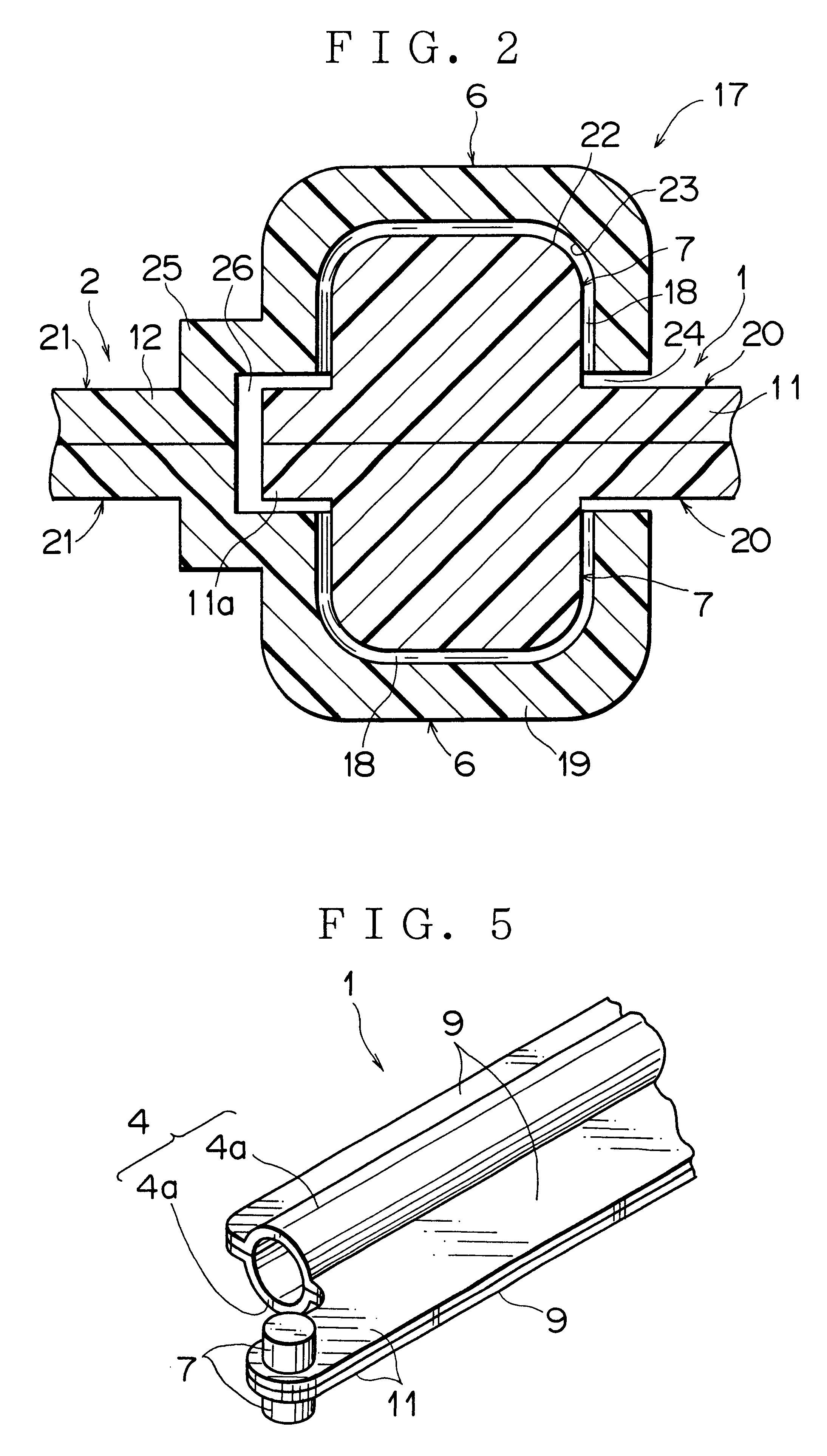
As shown in FIG. 1, the wiring harness bending mechanism of the present invention has a pair of link arms 1,2 made of synthetic resin. The link arms 1,2 integrally have respective tubular portions 4,5 to put a wiring harness 3 therethrough. The wiring harness 3 consists of single or plural electric wires. One end sides of respective link arms 1,2 pivotably engage each other by means of a pair of concavities 6 and a pair of convexities 7 (FIG. 2), and the other end side of each of the link arms 1,2 is secured with bolt 8.

Bodies of the link arms 1,2 consist of flat plate portions (plate portions) 9,10 and tubular portions 4,5, respectively. The above one end sides (i.e. link portion 17 sides) of wide flat plate portions 9a,10a of the respective link arms 1,2 extend to form respective extending portions 11,12, and the concavities 6 and the convexities 7 (FIG. 2) a...


PUM


Abstract

A wiring harness bending mechanism is provided, which includes: a wiring harness; and first and second link arms each having a tubular portion to put the wiring harness therethrough, wherein a pair of convexities are formed on the first link arm and a pair of concavities to engage the convexities are formed on the second link arm. The first link arm is formed of a pair of first divided link arms connected with a hinge portion and each having a convexity, and the second link arm is formed of a pair of second divided link arms connected with a hinge portion and each having a concavity. A plate portion is provided projectingly from each of the tubular portions, and the pair of convexities are arranged on one end side of one plate portion and the pair of concavities are arranged on one end side of the other plate portion. A fixing portion is provided on each of the other end sides of the respective plate portions for mounting the first and second link arms. The wiring harness is bendably exposed between the tubular portions. The first link arm is pivotably supported by a guide rail and the second link arm slidably engages the guide rail.

Description

1. Field of the InventionThe present invention relates generally to a wiring harness arranging structure to be applied to a sliding door of a motor vehicle or the like, and more particularly to a wiring harness bending mechanism wherein a pair of link arms equipped with a wiring harness are capable of bending integrally with the wiring harness along with an opening and closing operation of the sliding door so that the door is allowed to open and close.2. Description of the Related ArtFIG.9 shows bending structure of a wiring harness protector disclosed in Japanese Utility Model Registration Application Laid-open No.63-113416 as a first prior art. This wiring harness protector 60 is formed of a protector body 61 and a cover 62 both made of synthetic resin and is bendable with a thin hinge portion 63 arranged in its middle portion. The cover 62 engages the protector body 61 by means of an engaging projection 64 and an engagement frame 65.A wiring harness 66 is put in the protector bod...

Claims


Application Information

Patent Timeline
Patent Type & Authority Patents(United States)
IPC IPC(8): B60R16/02H02G11/00H02G3/04
CPCB60R16/0215H02G11/00
Inventor DOSHITA, KENICHI
Owner YAZAKI CORP
Why Eureka
Try Eureka