
Nerve movement and status detection system and method
a technology detection method, which is applied in the field of movement and status detection method and system, can solve the problems of limiting the ability of users to detect the response, and the difficulty of competing tasks of users
- Summary
- Abstract
- Description
- Claims
- Application Information
AI Technical Summary
Problems solved by technology
Method used
Image

Examples
Embodiment Construction
Throughout this description, the preferred embodiment and examples shown should be considered as exemplars, rather than as limitations on the present invention.
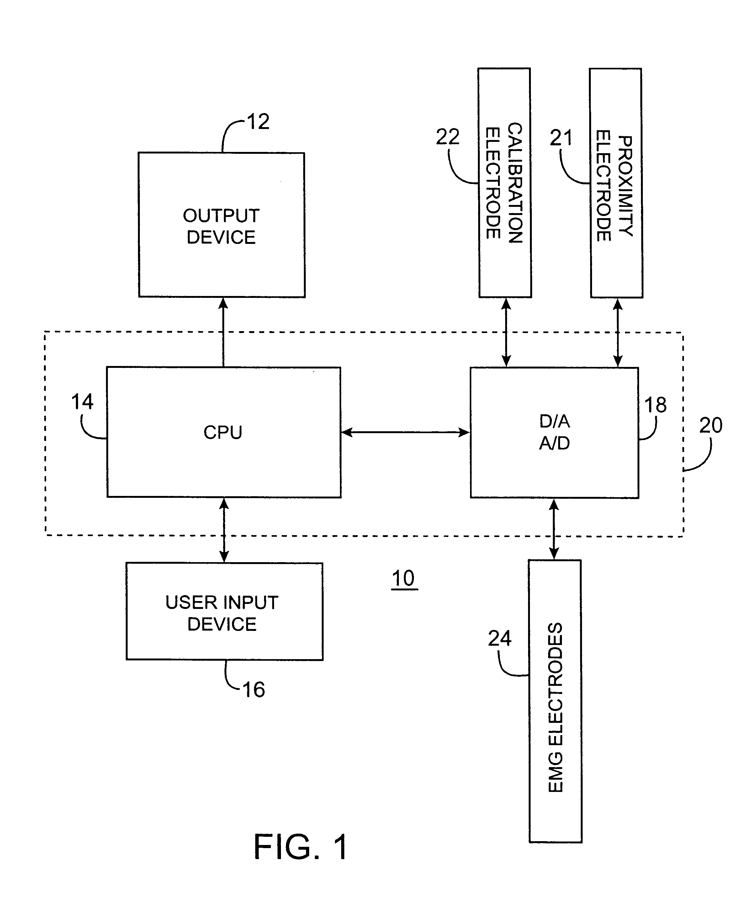
FIG. 1 is a diagram of an exemplary relative nerve movement and status system 10 in accordance with the present invention. The system 10 includes an output device 12, a user input device 16, a processor 20, a proximity electrode 21, a calibration electrode 22, and an electromyogram (EMG) electrode 24. The processor 20 includes a central processing unit ("CPU") 14 and a Digital to Analog converter ("D / A") and Analog to Digital Converter ("A / D") 18. The CPU 14 may be any microprocessor having sufficient processing power to control the operation of the D / A & A / D 18, and output device 12. The D / A & A / D 18 is any such device having a sufficient sampling rate and bit resolution to generate signals as described herein. The calibration electrode 22 is an electrode suitable for placement at a location where the distance to a nerve of ...
PUM
 Abstract
Description
Claims
Application Information