Connector reveal

a technology of connecting rods and connectors, applied in the direction of electrical apparatus casings/cabinets/drawers, coupling device connections, casings/cabinets/drawers details, etc., can solve the limitations of how precisely and reliably plastic parts can be manufactured, and the difficulty of aligning such subpanels to the rest of the case, etc., to achieve quick and easy affixed to the component housing, low cost of manufacture, and tight tolerances

Inactive Publication Date: 2004-11-09
APPLE INC
View PDF5 Cites 2 Cited by
  • Summary
  • Abstract
  • Description
  • Claims
  • Application Information

AI Technical Summary

Benefits of technology

An advantage of the present invention is that a housing subpanel is quickly and easily affixed to a component housing.
A further advantage of the present invention is that a housing subpanel is inexpensive to manufacture.
Yet another advantage of the present invention is that a housing subpanel and associated housing need not be constructed to extremely tight tolerances.
Still another advantage of the present invention is that the subpanel reveal is well aligned within an aperture provided therefor.
Yet another advantage of the present invention is that the subpanel reveal is well secured within the aperture provided therefor.

Problems solved by technology

In the prior art, it has frequently been difficult to align such subpanel to the rest of the case such that the subpanel aligns nicely with the surrounding case.
However, such precision manufacturing can be quite expensive and, indeed, there are limits to how precisely and reliably plastic parts can be manufactured.
Therefore, while significant expense has been incurred in an effort to solve this problem, a reliable and inexpensive solution has thus far evaded practitioners in the field.

Method used


Image

  • Connector reveal
  • Connector reveal
  • Connector reveal

Examples


Embodiment Construction

The embodiments and variations of the invention described herein, and / or shown in the drawings, are presented by way of example only and are not limiting as to the scope of the invention. Unless otherwise specifically stated, individual aspects and components of the invention may be omitted or modified, or may have substituted therefore known equivalents, or as yet unknown substitutes such as may be developed in the future or such as may be found to be acceptable substitutes in the future. The invention may also be modified for a variety of applications while remaining within the spirit and scope of the claimed invention, since the range of potential applications is great, and since it is intended that the present invention be adaptable to many such variations.

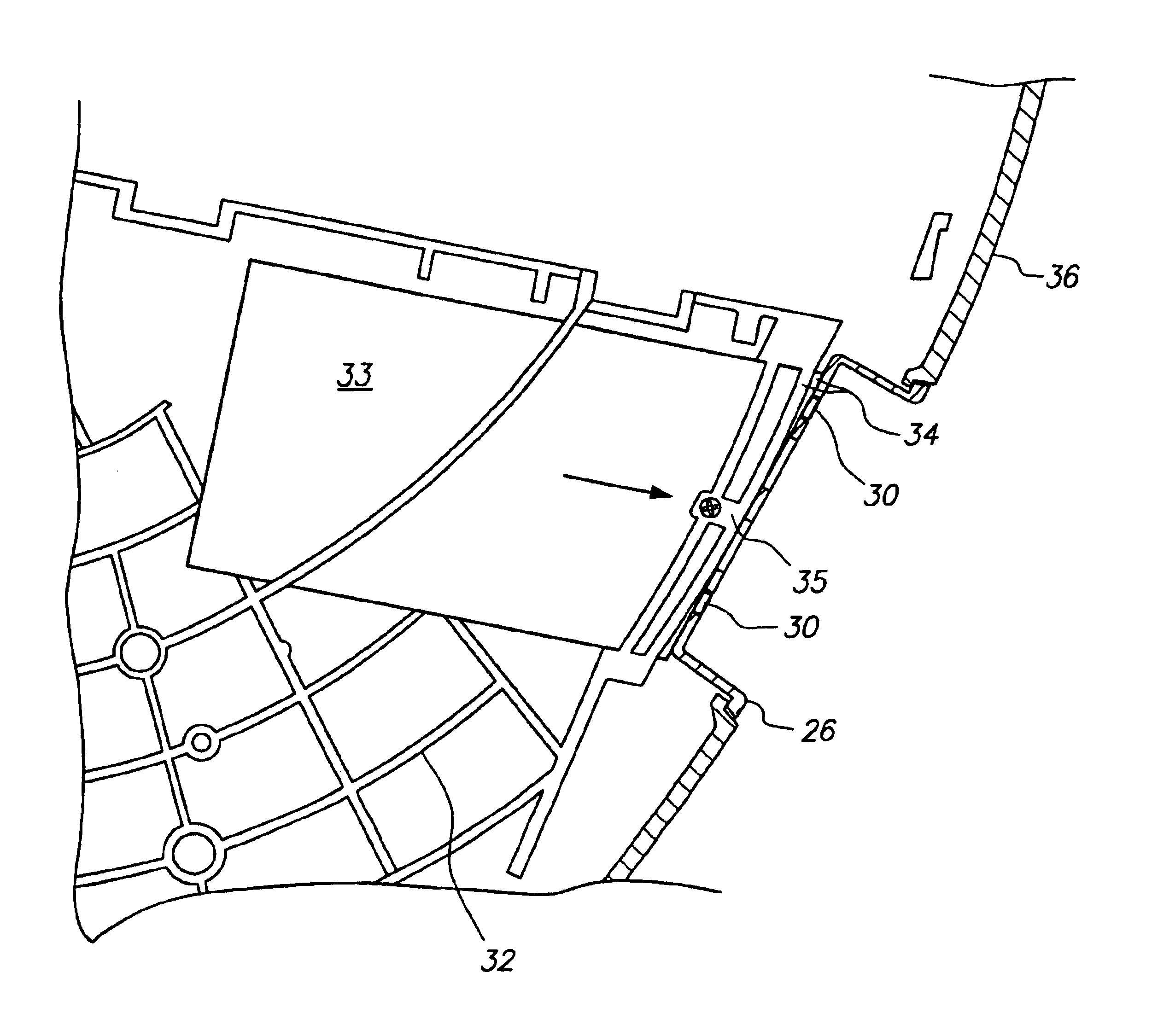
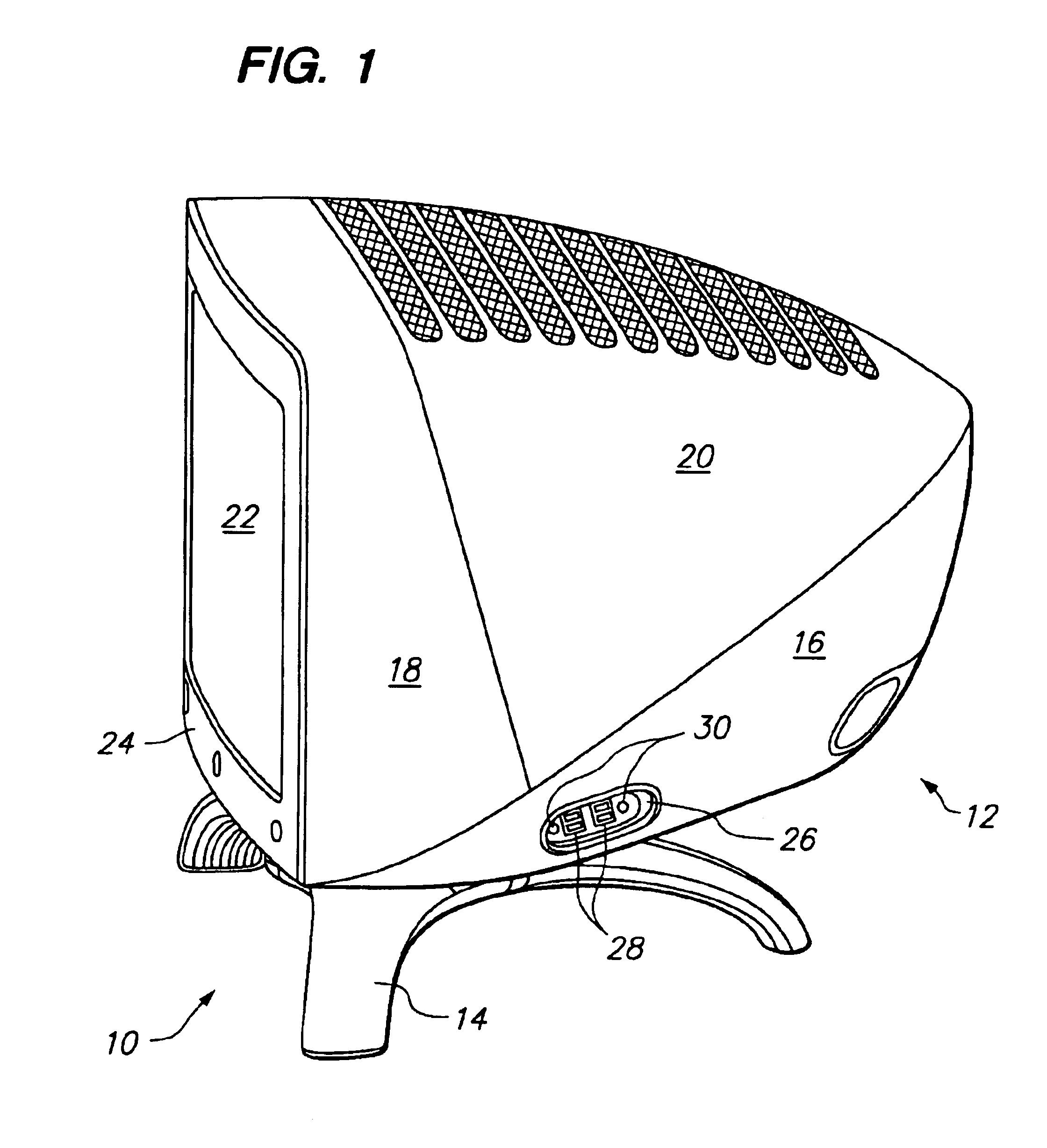
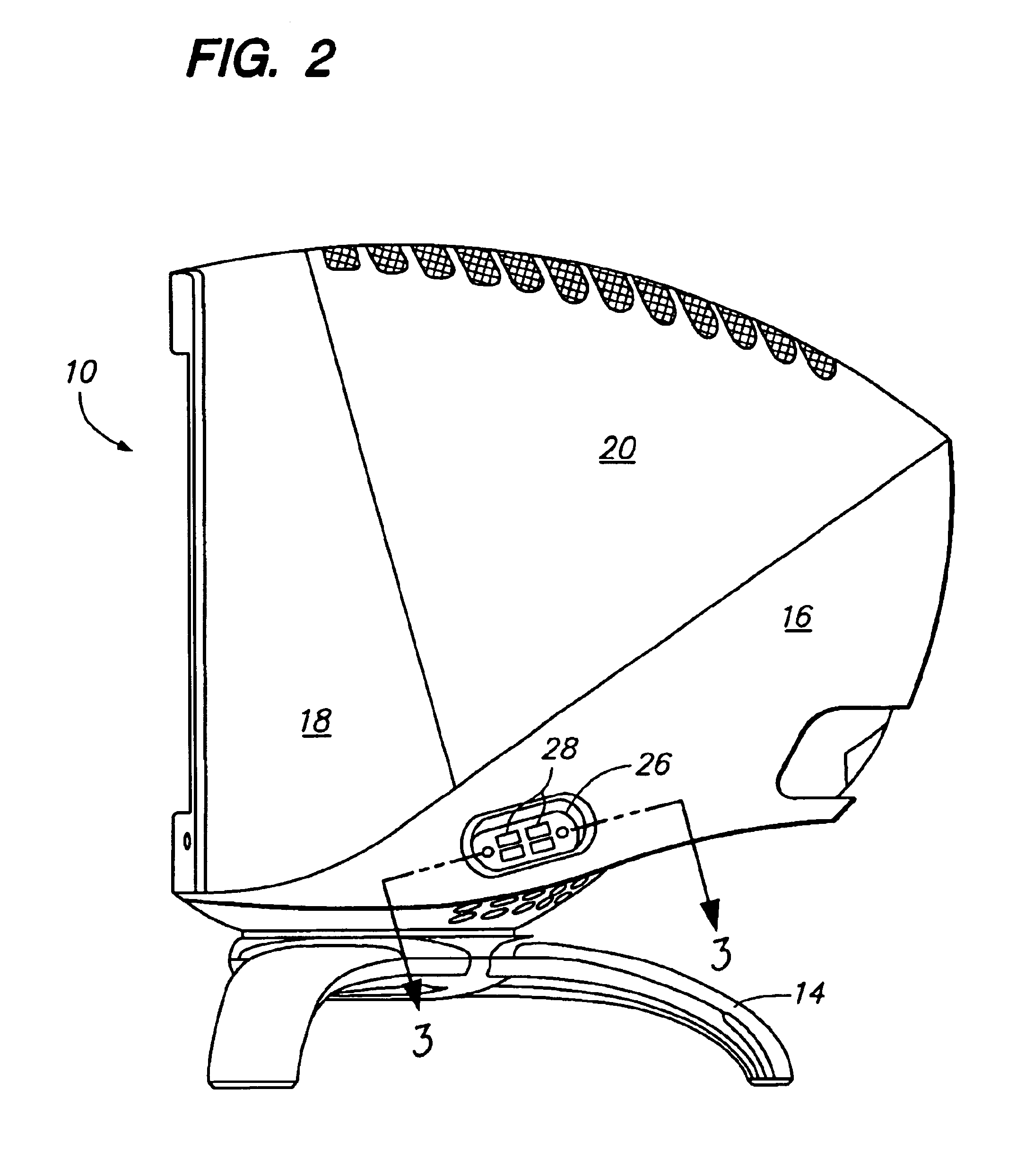
A known mode for carrying out the invention is a computer monitor constructed according to the present inventive method. The inventive computer monitor is depicted in a perspective view in FIG. 1 and in a side elevational view...


PUM

PropertyMeasurementUnit
flexibleaaaaaaaaaa
timeaaaaaaaaaa
spring tensionaaaaaaaaaa

Abstract

A case (12) for a computer monitor (10) having a tub (16) with a case aperture (38) therein adapted for receiving a subpanel (26). The subpanel (26) has a plurality of electrical connectors (28) which are user accessible thereby. A beveled flange (40) on the subpanel (26) is received within a receiving flange (44) on the case aperture (38). A structural grid (32) within the case (12) has a flexible portion (34) which includes a can (33) coupled to a flexible arm (35), and which has a screw receiving aperture (42) therein such that a screw (30) is passed through a subpanel screw aperture (48) in the subpanel (26) and secured within the screw receiving aperture (42), thereby flexing the flexible portion (34) to hold the subpanel (26) firmly within the case aperture (38).

Description

The present invention relates to the field of mechanical construction, and more particularly to an improved connector reveal for an electronic component case. The predominant current usage of the present inventive improved connector reveal is in the construction of a computer monitor case, wherein it is desirable to have a means to quickly and inexpensively affix a case subpart to the case.In the construction of electronic component devices, such as computers, computer monitors, and the like, it is frequently required to have electrical connectors which are accessible from the outside of the case. It is known in tho art to attach such connectors to a body subpanel, sometimes a recessed body panel, such that such body panel can be constructed as a separate subcomponent which is affixed to the case during the final assembly thereof. In the prior art, it has frequently been difficult to align such subpanel to the rest of the case such that the subpanel aligns nicely with the surroundin...

Claims


Application Information

Patent Timeline
Patent Type & Authority Patents(United States)
IPC IPC(8): H01R13/74
CPCH01R13/74H01R13/748H02G3/18Y10T29/49904Y10T29/49963Y10T29/49826
Inventor HEIRICH, DOUGLAS L.
Owner APPLE INC
Why Eureka
Try Eureka