Seam cover system for crown molding installations

a crown molding and sealing system technology, applied in the direction of covering/lining, walls, natural patterns, etc., can solve the problems of unresolved difficulties and drawbacks, undesirable joint separation, and high visible flaws, and achieve quick and easy installation with ease and simplicity, quick and easy installation, and quick and easy installation. the effect of ease and speed

Inactive Publication Date: 2009-03-12
FOCAL POINT PRODS
View PDF20 Cites 13 Cited by
  • Summary
  • Abstract
  • Description
  • Claims
  • Application Information

AI Technical Summary

Benefits of technology

[0017]In the present invention, support brackets are mounted in any desired location by employing-threaded screw members, with the desired lineal cornice or crown molding strips, inside and / or outside corner seam covers, and lineal seam covers being mounted in the desired positions by merely affixing these components to their associated bracket members. In this way, the entire cornice or crown molding system is quickly and easily installed with ease and simplicity using only commonly employed screwdrivers.
[0018]In the present invention, any desired cornice or crown molding configuration is selected in preconstructed elongated lengths, and once a particular room has been measured for determining the length of the material needed, the preconstructed elongated length of crown molding is cut to the desired size, without requiring a mitered cut. If possible, the length of material extends from one wall to another, requiring only the installation of corner seam covers at opposed ends thereof. In this regard, a plurality of brackets are easily mounted along the top edge of a wall, directly adjacent to the ceiling and, once installed, the elongated lengths of the desired crown molding is quickly and easily secured in place by engaging the elongated lengths of crown molding with the support brackets mounted to the wall.
[0019]In order to complete this installation, corner brackets are mounted in each opposed corners of the wall, directly adjacent to the elongated lengths of the crown molding and, once installed, corner seam covers are mounted to the support brackets to complete the installation. In the preferred embodiment, each corner seam cover is constructed for frictional engagement with the corner bracket and incorporates a pre-formed, integral mitered configuration, thereby assuring the installation of the corner seam cover without the use of any adhesives, nails, or other fastening elements and without requiring any mitering. In addition, the corner seam cover is constructed to extend beyond the terminating edge of the molding strip itself, thereby preventing the need for any mitering or joining of abutting edges. In this way, installation ease and speed are realized.
[0020]In some installations, the size of the room prevents a continuous elongated strip of crown molding material to be employed. In these instances, crown molding lengths are mounted adjacent to each other with a space therebetween, and a support bracket mounted in the space. In order to complete the installation, a lineal seam cover is employed which is quickly and easily affixed to the support bracket, covering both terminating ends of the crown molding strip and providing a desirable, visually pleasing result. In this regard, the seam cover extends beyond both terminating edges of the adjacent crown molding strips, thereby eliminating any need for filling abutting edges or joints, while providing an overlap of the seam cover with the molding strips for producing a visually distinctive and aesthetically pleasing result.
[0021]In the present invention, each of the crown molding strips, inside and outside corner seam covers, and lineal seam cover members are constructed in a wide variety of decorative, visually distinctive configurations. As a result, individuals are able to select from numerous product choices in order to achieve an installation which satisfies the personal desires of the customer. In this way, any desired visual appearance for a particular room is capable of being satisfied, with the complete installation of the decorative molding system of the present invention being completed quickly and easily, without requiring the use of any nails, adhesives, or other undesirable fasteners and without requiring any mitered cuts to be made. In addition, the present invention eliminates any visible holes from nails or screws, thereby enhancing the overall aesthetic appeal of the final installation.

Problems solved by technology

Although substantial interest has been generated focusing on the use and installation of various molding elements in existing homes as well as homes being professionally constructed, difficulties and drawbacks are frequently encountered in the installation of molding elements, which difficulties and drawbacks have not been resolved.
However, due to cutting errors, as well as typical home construction, precise 90° corners are not always present and gaps occur between adjacent molding portions, creating highly visible flaws.
Furthermore, even if a high degree of technical skill is employed to achieve precise miter corners in the installation of molding strips, the molding expands and contracts as the ambient temperature changes causing undesirable joint separation.
Typically, virtually all molding installation experiences shrinkage due to contraction and expansion from heat and cooling.
In this regard, once the elongated molding strip has been installed, temperature changes occur causing the molding material to expand or contract.
These changes inevitably cause gaps to occur between adjacent strips or in corner connection points, which gaps are frequently unsightly and detract from the visual aesthetic appeal of the molding components.
An additional problem found in prior art constructions is a requirement that crown molding, or any other molding components, are mounted in place by use of adhesives or fastening materials such as nails.
In particular, the use of nails causes unsightly holes to be formed in the molding members, which are incapable of being totally hidden and result in unsightly and unpleasant visual effects.
In addition, the use of adhesives adds an additional level of difficulty to the installation process, often causing unwanted spattering and drops to be formed which are difficult to remove.
Furthermore, the material employed for adhesives is often corrosive and / or toxic, thereby requiring special treatment and handling, as well as being environmentally unfriendly.
Although substantial effort has been expended in developing prior art products which have attempted to reduce or eliminate these prior art problems, no prior art system has been capable of eradicating these problems.
Consequently, molding installation occurring today continues to suffer from all of the drawbacks and difficulties detailed above.

Method used


Image

  • Seam cover system for crown molding installations
  • Seam cover system for crown molding installations
  • Seam cover system for crown molding installations

Examples


Embodiment Construction

[0038]By referring to FIGS. 1-13, along with the following detailed discussion, the preferred construction and operation of the cornice and crown molding system of the present invention can best be understood. Although this disclosure fully details the preferred embodiment of the present invention, alterations and variations in the embodiment provided herein can be made without departing from the scope of this invention. Consequently, it should be understood that the disclosure of the embodiment shown in FIGS. 1-13 and discussed in the following disclosure are provided for exemplary purposes only and should not be interpreted in a limiting sense.

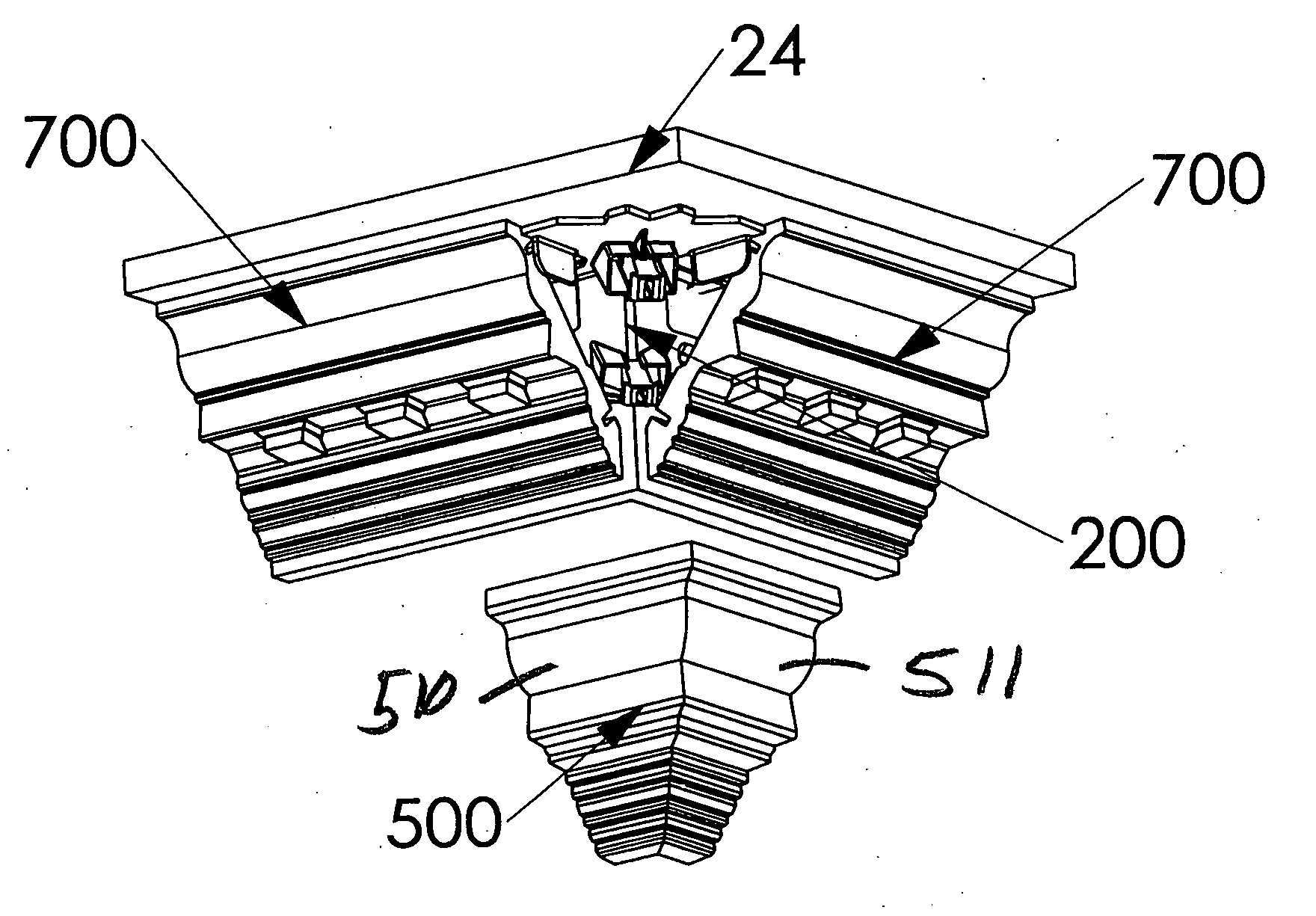
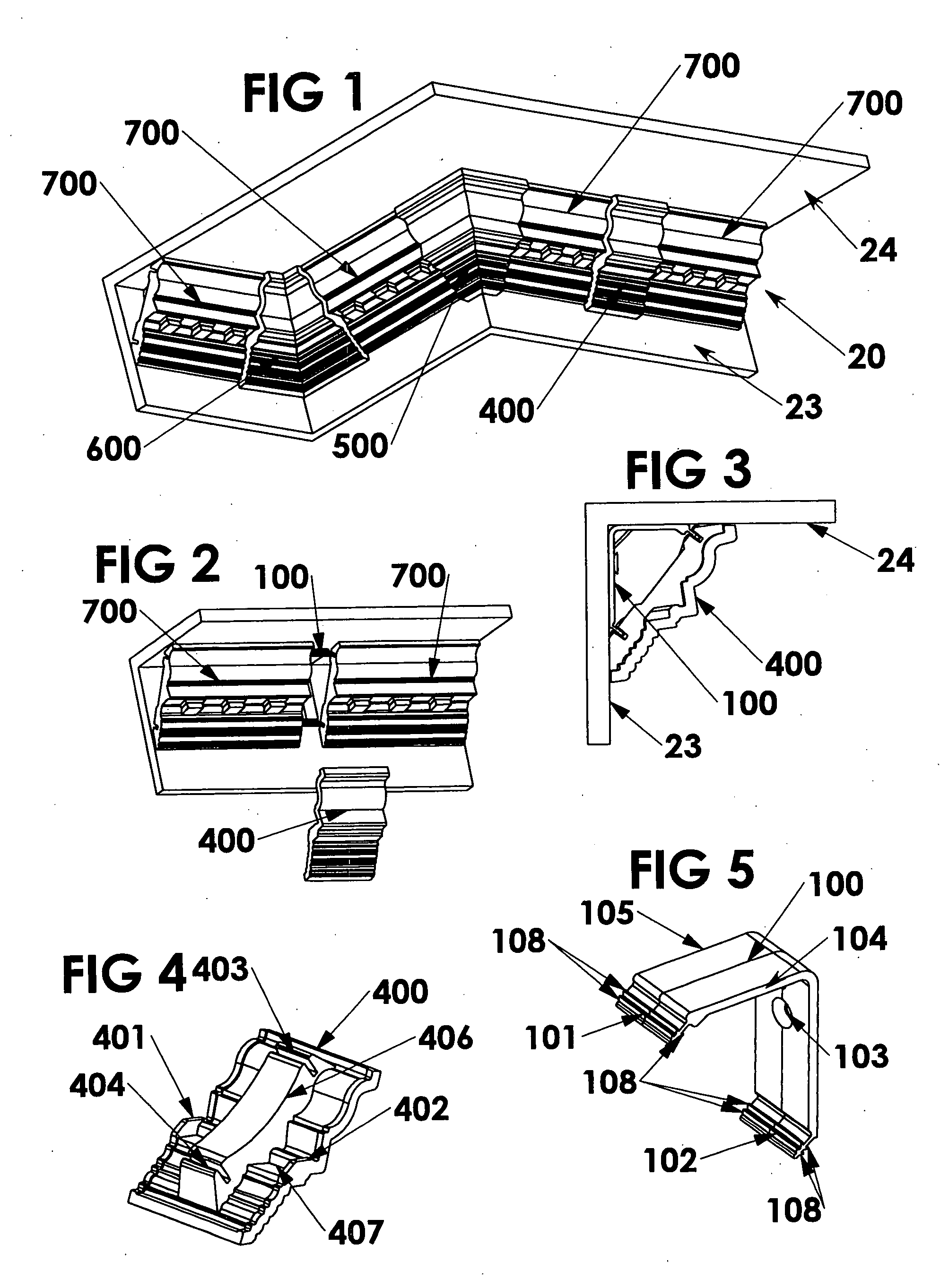
[0039]In FIG. 1, a typical installation of cornice or crown molding system 20 of the present invention is provided, depicting a complete assembly for a portion of a room. In this installation, all of the visible components forming cornice or crown molding system 20 are shown, mounted in place to the top portion of wall 23 at its juncture wit...


PUM


Abstract

By providing a plurality of support brackets which are quickly and easily mounted to any desired surface and are constructed for receiving and supportingly retaining elongated, lineal crown molding strips, inside and outside corner seam covers, and lineal seam covers, each of which are formed from a wide variety of decorative and visually distinctive appearances, a cornice or crown molding system is achieved which is capable of being quickly and easily installed in any desired location by any unskilled individual, without requiring the use of mitered corners, abutting junctures, nails, adhesives, and the like. By employing a combination of the components of the present invention, any desired location can be quickly and easily decorated with a completely installed molding system for enhancing the visual and aesthetic appeal of any room or building.

Description

[0001]This invention relates to molding systems for installation in homes, offices, and other buildings and, more particularly, to cornice or crown molding systems which are quickly and easily mounted in position, without requiring the use of adhesives, nails, other similar fastening elements.BACKGROUND ART[0002]Homeowners are continuously upgrading their residences in order to improve the visual appeal of their homes. Frequently, these upgrades include decorative or aesthetic improvements or enhancements which are employed for making homes more visually attractive both for the homeowner as well as for resale of the home. In addition, similar improvements or enhancements are also employed by home builders in order to impart greater interest and excitement to a newly built home to enable the home to be more attractive and saleable.[0003]Although these improvements and enhancements may take many different forms, frequently, homeowners and home builders add decorative features to a hom...

Claims


Application Information

Patent Timeline
Patent Type & Authority Applications(United States)
IPC IPC(8): E04F13/24
CPCE04F19/0436
Inventor OUYANG, TIANHONGROBINSON, KENNETH L.
Owner FOCAL POINT PRODS
Why Eureka
Try Eureka